In this tutorial, we learn how to get started with NodeMCU ESP8266. We program the Nodemcu board using the Arduino IDE.
NodeMCU is just like the Arduino board with onboard Wi-Fi. It is small in size than Arduino Uno but similar to Arduino Nano. It is capable to connect to the internet using Wi-Fi and you can take your projects online.
It runs on the ESP8266 Wi-Fi Soc from Espressif Systems, and hardware which is based on the ESP-12 module. Lua scripting language is used by the firmware.
Read More about NodeMCU.
Components Needed
- NodeMCU (ESP8266) Board.
- LEDs.
- Breadboard.
- Arduino IDE.
Setting Up Arduino IDE for NodeMCU
Download and Install Arduino IDE:
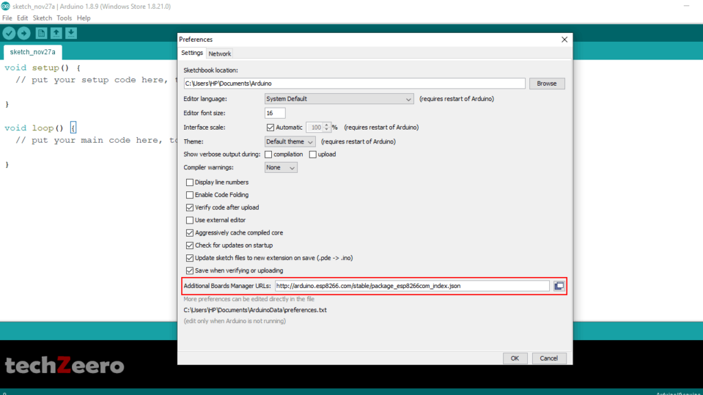
- Now go to Files >> Preferences and paste the below link in Additional Boards Manager URLs.
http://arduino.esp8266.com/stable/package_esp8266com_index.json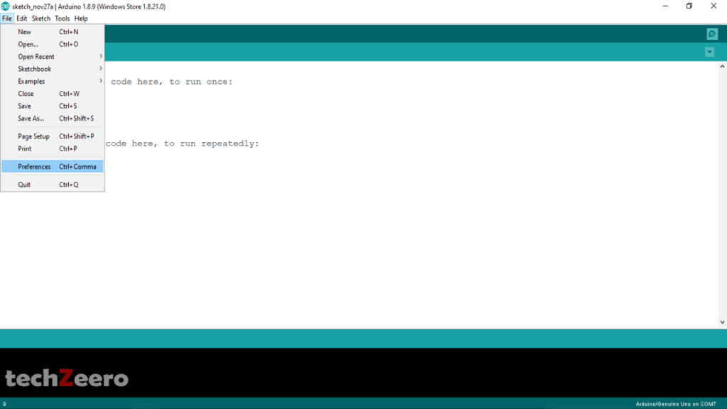
Installing the ESP8266 Board:-
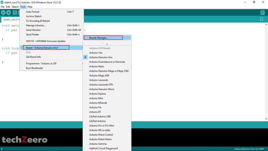
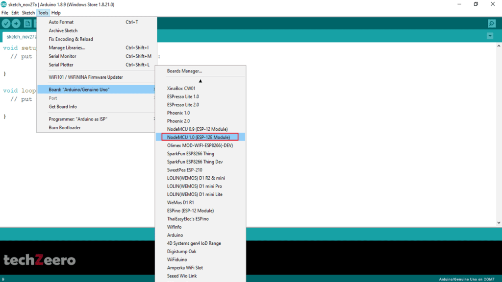
- Go to Tools >> Board >> Board Manager (at the top in the list).
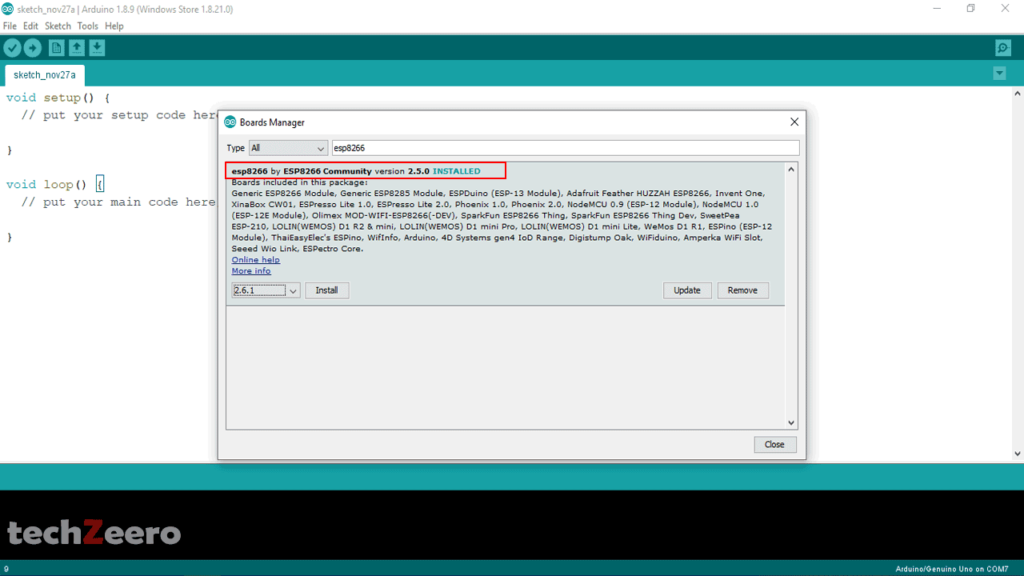
- Search or Scroll down to Find ESP8266.
- Click on install.
Select Board (NodeMCU 1.0):-
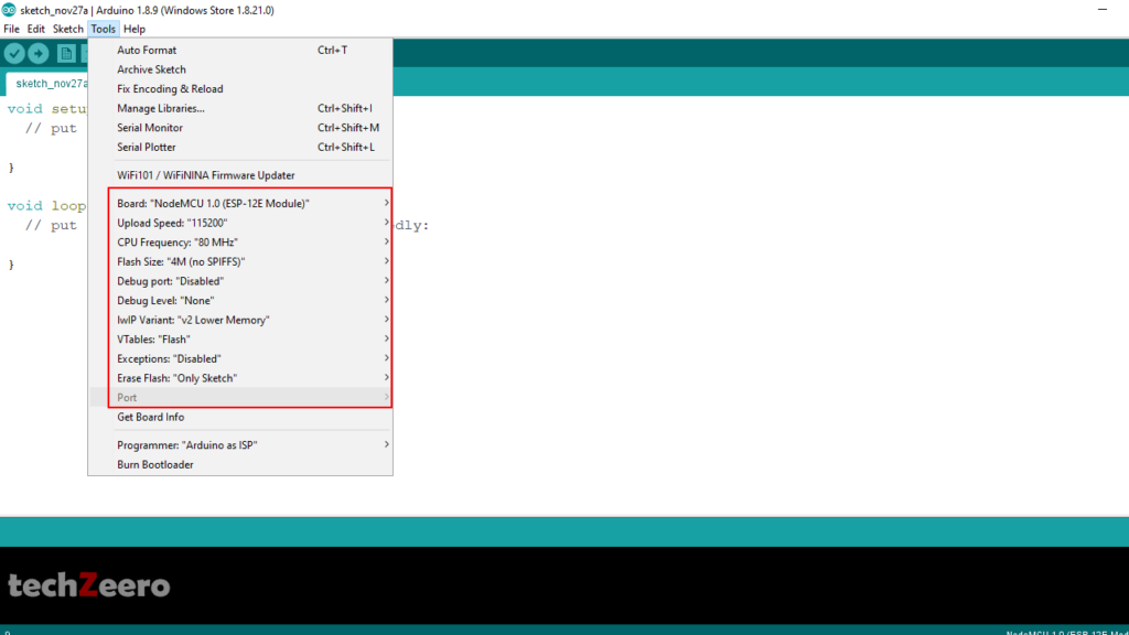
After Selecting the Board, follow below settings:-
- Upload Speed: “115200”
- CPU Frequency: “80Mhz”
- Flash Size: “4M (no SPIFFS)”
- Debug Port: “Disabled”
- Debug Level: “None”
- IWIP Variant: “V2 Lower Memory”
- VTables: “Flash”
- Exceptions: “Disabled”
- Erase Flash: “Only Sketch”
- Port: “Where the device is connected”
Code for Blink Builtin LED of NodeMCU
- Goto Files >> Examples >> ESP8266
- Select the Blink Program and upload it.
NodeMCU GPIO Pins
| Pin Names on NodeMCU Board | ESP8266 Internal GPIO Pin Number |
|---|---|
| D0 | GPIO16 |
| D1 | GPIO5 |
| D2 | GPIO4 |
| D3 | GPIO0 |
| D4 | GPIO2 |
| D5 | GPIO14 |
| D6 | GPIO12 |
| D7 | GPIO13 |
| D8 | GPIO15 |
| RX/D9 | GPIO3 |
| TX/D10 | GPIO1 |
| SD2D11 | GPIO9 |
| SD3D12 | GPIO10 |
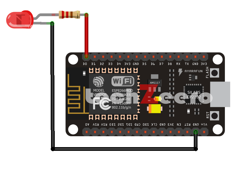
Circuit Diagram For Blinking External LED using NodeMCU
In the below circuit, we connect the led to D0 pin whose GPIO number is 16.
Code For Blinking External LED using NodeMCU
For blinking an external led using NodeMCU upload the below code.