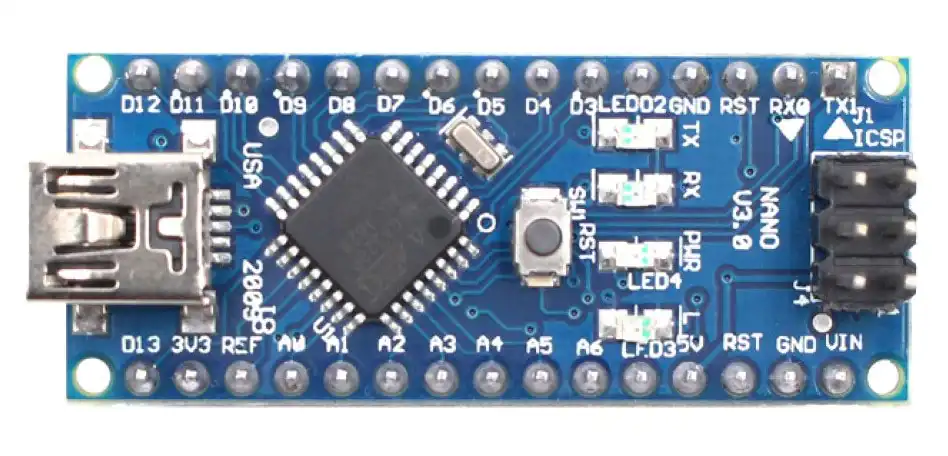
What is Arduino Nano
The Arduino Nano is a compact, powerful microcontroller board designed for small-scale electronic projects. It offers the same core functionality as larger Arduino boards but in a much smaller footprint. Built around the ATmega328P microcontroller, the Nano is perfect for space-constrained applications like wearables, IoT devices, and home automation.
One of the most attractive features of the Arduino Nano is its ease of use, making it ideal for both beginners and advanced users. Whether you’re building a robot, sensor module, or automation system, this little board can bring your project to life.
Despite its size, the Nano supports a wide range of applications—from controlling LEDs and motors to interfacing with sensors and communication modules.
🔌 Unlike the Arduino Uno, the Nano lacks a power jack and uses a mini-B USB port for power and programming.
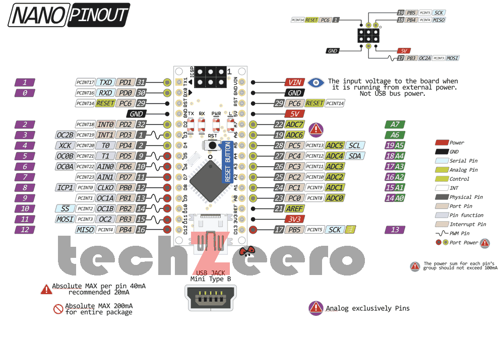
Arduino Nano Pinout
Understanding the pin configuration of Arduino Nano is essential for any electronics project. This small board includes 30 pins in total. These include:
- 14 digital I/O pins
- 8 analog input pins
- Power and reset pins
- SPI and I2C communication pins
This versatile layout allows you to connect multiple devices and modules to your project.
14 Digital I/O Pins (D0 to D13)
There are 14 digital pins on the Nano. They can be used as either inputs or outputs. Among these:
- 6 PWM pins (D3, D5, D6, D9, D10, D11) support Pulse Width Modulation, which lets you control brightness, motor speed, and more.
- Pins D0 (RX) and D1 (TX) are used for serial communication.
Digital Pins (D2 to D13)
- Used for input and output of digital signals.
- Pins D3, D5, D6, D9, D10, and D11 support PWM (Pulse Width Modulation) for tasks like LED dimming and motor speed control.
Analog Pins (A0 to A7)
- Connects analog sensors such as temperature or light sensors (LDR).
- Inputs analog values (0–1023) using 10-bit ADC (Analog-to-Digital Converter).
Power Pins
- Vin: Input voltage (7–12V) when powered externally.
- 5V: Regulated output voltage. Used to power external modules.
- 3.3V: Output voltage, max 50 mA. For low-power sensors.
- GND: Ground pins.
- IOREF: Provides the operating voltage reference of the board (either 3.3V or 5V).
⚠️ Note: Avoid supplying voltage directly to the 5V or 3.3V pins, as it bypasses the onboard voltage regulator and can damage the board.
The Nano also includes a mini-USB port for easy programming and power supply. An onboard voltage regulator allows flexibility in power sources—USB or external.
Arduino Nano Pin Configuration Diagram (Optional)
Communication Interfaces
The Nano supports multiple types of communication for interfacing with other devices.
🔸 SPI Communication
The Nano includes SPI communication support through pins D10 (SS), D11 (MOSI), D12 (MISO), and D13 (SCK). This high-speed protocol is ideal for connecting SD cards, displays, and other SPI-enabled devices.
🔸 I2C Communication
For simpler, two-wire connections, the board also supports I2C communication. This uses A4 (SDA) and A5 (SCL) pins. I2C is commonly used with OLED displays, RTC modules, and sensors like BME280.
Technical Specifications
| Microcontroller | ATmega328 |
| Operating Voltage | 5 V |
| Flash Memory | 32 KB of which 2 KB used by bootloader |
| SRAM | 2 KB |
| Clock Speed | 16 MHz |
| Digital I/O Pins | 14 (6 of which are PWM) |
| Analog IN Pins | 8 |
| EEPROM | 1 KB |
| DC Current per I/O Pins | 40 mA (I/O Pins) |
| Input Voltage | 7-12 V |
| PWM Output | 6 |
| Power Consumption | 19 mA |
| PCB Size | 18 x 45 mm |
| Weight | 7 g |
Vin: This is the input voltage pin used when the Arduino board is powered through an external source. In this case, you can supply voltage directly through this pin. However, if you’re supplying power via the USB connection or the power jack, then the board accesses voltage through this same pin.
5V: This pin provides a regulated 5V output. Therefore, you can use it to supply 5V power to sensors or other modules.
3V3: This pin gives an output of 3.3V. However, the maximum current it can provide is limited to 50 mA. As a result, it is best used for low-power components.
GND: These are the ground pins. In every circuit, at least one GND connection is required to complete the circuit.
IOREF: On the Arduino board, this pin provides a reference voltage used by the microcontroller. In fact, a properly configured circuit can read the IOREF voltage and determine whether the board operates at 5V or 3.3V. Consequently, it can choose the correct power level or activate a voltage translator for compatible output.
Note:- Do not supply voltage via the 5V or 3.3V pins, it bypasses the regulator and can damage the board. We don’t advise it.
Pros and Cons of Using Arduino Nano
Like all technology, the Arduino Nano has its strengths and limitations. Here’s a quick overview:
✅ Pros:
- Small and lightweight
- Easy to program and use
- Affordable and widely available
- Compatible with many sensors and modules
- Supported by a large community
❌ Cons:
- No power jack
- Limited memory compared to larger boards
- Fewer pins for complex applications
- Sensitive to voltage supply issues
However, for most hobby and beginner projects, the benefits far outweigh the drawbacks.
Final Thoughts
To sum up, the Arduino Nano pinout and its well-designed pin configuration make it a great choice for both beginners and experienced developers. Its compact size, low cost, and strong feature set make it one of the most popular boards in the Arduino family.
If you’re working on a small project, and you need something reliable and easy to use, the Arduino Nano might be the perfect fit.