Introduction to Potentiometer and LCD Displays
In this blog post, we’re going to explore how you can use potentiometers and LCD Display to create a fun and interactive project. Whether you’re a seasoned hobbyist or just starting out, this guide will walk you through the steps of displaying potentiometer readings on an LCD display.
We will use an LCD 16×2 display in this tutorial and we will need two potentiometers, one to adjust the LCD brightness and one to get readings.
The Arduino uses an analog pin to read the sensor values. So the potentiometer we want to read will connect it to the analog pin of the Arduino.
- Also, Read:- How to use an LCD Display with Arduino.
Components List
- LCD 16 x 2 Display
- Arduino Uno
- 2 x Potentiometer 10kOhms
- Jumper Wires
- Breadboard
- Resistors
Pin Connections
Connection of Arduino and LCD
| Pin No. | LCD Pins | Arduino Pins |
|---|---|---|
| 1 | VSS/GND | GND |
| 2 | VDD/VCC | 5v |
| 3 | V0 | Potentiometer Vout |
| 4 | RS | 12 |
| 5 | RW | GND |
| 6 | E | 11 |
| 7-10 | D0-D3 | No connection |
| 11 | D4 | 5 |
| 12 | D5 | 4 |
| 13 | D6 | 3 |
| 14 | D7 | 2 |
| 15 | A/LED+ | 5v |
| 16 | K/LED- | GND |
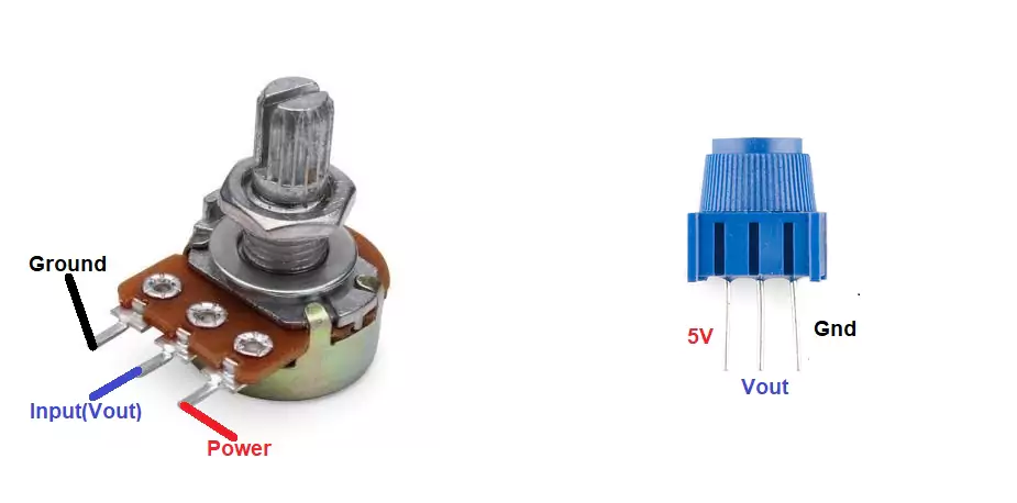
Connect the LCD Potentiometer Vin and GND with Arduino 5v and GND respectively.
Connection Of Arduino and Second Potentiometer
| Pin No. | Potentiometer Pins | Arduino Pins |
|---|---|---|
| 1 | 5V / Vin | 5V |
| 2 | GND | GND |
| 3 | Wiper / Vout | A0 |
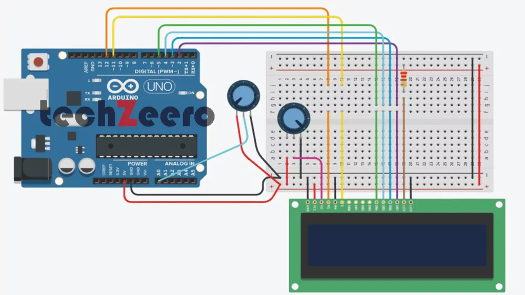
Circuit Diagram for Potentiometer with LCD Display
Setting up the circuit to display potentiometer readings on an LCD display is a crucial step in this project. It involves connecting the components correctly to ensure smooth operation.
Begin by gathering all the necessary materials, including an Arduino board, a potentiometer, an LCD display, jumper wires, and a breadboard. Lay out your workspace with ample room to work comfortably.
Next, carefully place the components on the breadboard according to the circuit diagram. Double-check each connection to avoid any potential issues later on.
Once everything is set up physically, it’s time to move onto coding the Arduino. This will enable communication between the potentiometer, LCD display, and microcontroller for accurate readings.
Follow instructions closely when writing and uploading the code. Test each component individually before integrating them into one system for optimal performance.
Coding the Arduino for Potentiometer Readings on LCD
When it comes to coding the Arduino for potentiometer readings, the possibilities are endless. With just a few lines of code, you can unlock a whole new world of data visualization and control.
Start by initializing the necessary libraries for reading analog inputs and controlling the LCD display. Then, create variables to store the analog input values from the potentiometer.
Next, set up the serial communication to monitor your readings in real-time on your computer. This step is crucial for debugging and fine-tuning your code.
Utilize conditional statements and mapping functions to translate the analog input values into meaningful information that can be displayed on the LCD screen.
Experiment with different display formats such as bar graphs or numerical values to enhance user experience and readability.
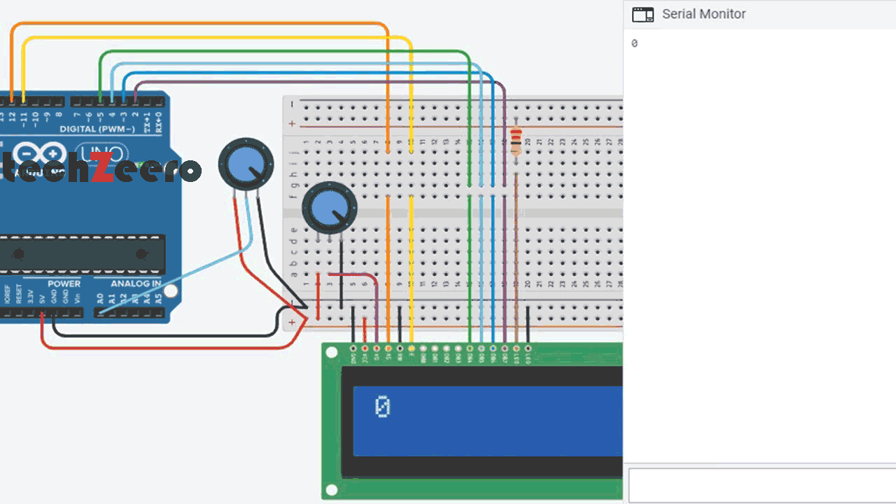
Upload the below code in Arduino and get the adjust the potentiometer to see different readings.
Output
Once your circuit is set up and the potentiometer readings are being accurately captured by the Arduino, it’s time to take things one step further. Displaying these readings on an LCD screen adds a visual element that enhances the overall project experience.
By coding the Arduino to transmit the potentiometer values to the LCD display, you can create a real-time feedback system that showcases changes in resistance as you adjust the knob of the potentiometer. This dynamic interaction bridges the gap between analog input and digital output.
Troubleshooting Tips
Having trouble getting your potentiometer readings to display correctly on the LCD? Don’t worry, troubleshooting common issues can help you get back on track with your project.
- First, double-check all connections to ensure everything is properly plugged in. Sometimes a loose wire or incorrect pin assignment can cause issues with the readings.
- Next, verify that your code is error-free. Oftentimes, a simple syntax mistake can lead to inaccurate readings or no display at all. Take a closer look at your coding lines related to reading the potentiometer values and displaying them on the LCD.
- If everything seems fine hardware and software-wise, consider testing each component individually. This can help pinpoint if there’s an issue with either the potentiometer or the LCD display itself.
- Make sure you’re using compatible components that are suitable for each other. Sometimes mismatched parts can lead to compatibility issues causing discrepancies in readings.