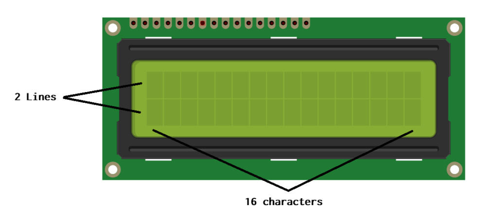
The LCD Display 16×2 Module is a popular choice for displaying text and numbers in various electronic devices. It consists of 16 columns and 2 rows of characters, allowing for clear and easy-to-read information presentation. This module utilizes liquid crystal technology to produce sharp, high-contrast images on its screen.
Ideal for projects requiring a compact display solution, applications of the 16×2 LCD module such as digital clocks, thermometers, and small gadgets. Its simple interface makes it user-friendly even for beginners in electronics.
With its backlight feature, this module ensures readability under different lighting conditions. The ability to customize characters further enhances its versatility in displaying unique symbols or icons.
Related Articles:
In LCD 16×2 there are 2 lines with 16 characters in each line. Each character is of 5×8 (column x row) pixel matrix.
Pin Description
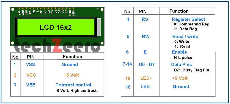
The module typically consists of 16 pins in total, with each serving a specific purpose in displaying information on the screen.
Among these pins are power supply pins like VCC and GND, which provide the necessary voltage for the module to function correctly. Additionally, there are control pins such as RS (Register Select), RW (Read/Write), and E (Enable) that help manage data flow and communication between the microcontroller and display.
Furthermore, there are data pins D0 to D7 responsible for transmitting information from the microcontroller to the display. These pins play a vital role in sending characters or commands to be shown on the screen accurately.
- VSS:- connect to Arduino ground pin.
- VCC:- connect to Arduino 5V pin for power supply.
- VEE/VO:- it controls the brightness and contrast of LCD. Using a potentiometer we adjust the contrast.
- RS (Register Select):-
- RS = 0:- if RS is 0 then Data on the D0 to D7 pins is consider as a command.
- RS = 1:- if RS is 1 then Data on the D0 to D7 pins is consider to display on LCD.
- RW (Read/Write):-
- RW = 0:- Write data to the LCD.
- RW = 1:- Read data from the LCD.
- E (Enable):- This pin enables the display. When this pin is HIGH, the LCD is processing the incoming data.
- D0 to D7:- Those are data pins which are used to send 8-bits data and commands to LCD.
- LED+ and LED- :- Controls to LCD backlight.
Applications of the 16×2 LCD Display Module
The 16×2 LCD display module is a versatile component that finds applications in various fields.
- One prevalent application is in the field of home automation where the LCD display can show real-time data such as temperature, humidity levels, or even act as a user interface for controlling smart devices.
- In industrial settings, these modules are employed in machinery interfaces displaying critical information like production statistics or machine statuses at a glance.
- Moreover, they are utilized in consumer electronics like digital clocks, thermometers, and small appliances to provide users with visual feedback.