Introduction to Relay Module with Arduino
In this blog post, we will dive into how you can integrate a Relay Module with Arduino to control high-power devices and automate your projects like never before.
A relay is an electric switch that can be turned on or off. Relays are used to control a circuit by a separate low power signal or, controlled several circuits by one signal.
How Does a Relay Module Work?
Relay modules are essential components in automation and control systems, acting as switches that turn circuits on or off. They work by using an electromagnet to open or close the switch contacts. When a small electrical current flows through the relay coil, it creates a magnetic field that attracts an armature, either opening or closing the circuit.
This mechanism allows relay modules to control high-power devices with low-power signals from microcontrollers like Arduino. The signal triggers the relay to actuate, providing isolation between the input and output circuits. This feature is crucial for protecting delicate electronic components from damage due to voltage spikes or feedback loops.
In essence, a relay module serves as a mediator between different voltage levels or types of circuits.
Types of Relay Modules
Relay modules come in various types, each designed for specific applications.
- One common type is the electromagnetic relay module. It uses an electromagnet to mechanically operate the switch contacts. Another type is the solid-state relay module, which uses semiconductor devices like transistors to switch on and off without any moving parts.
- There are also latching relay modules that stay in their last switched state even after power loss.
- Timer relays allow control over timing functions.
- Protective relays safeguard electrical systems from faults.
- Signal relay modules are ideal for low-power signal switching tasks.
Furthermore, you can find voltage sensing relay modules that trigger based on voltage levels and dual-coil relay modules for bidirectional switching needs.
Components Needed
- Arduino Uno.
- Relay Module 5V.
- LDR Sensor.
- Jumper Wires.
- Bulb.
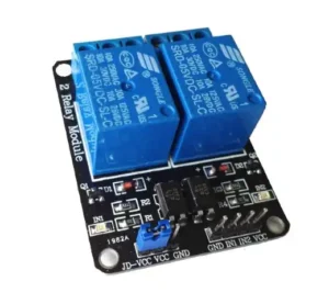
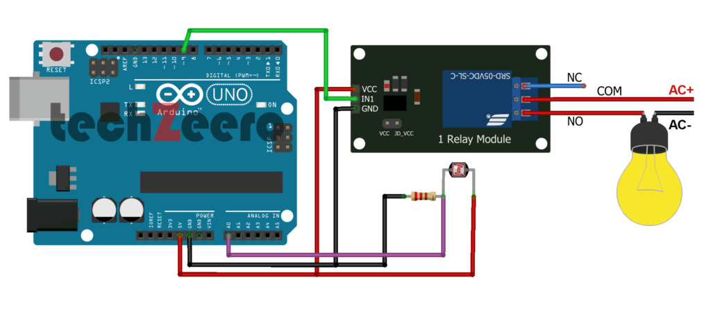
Pinout of Relay Module
The typical relay module consists of a VCC (power supply), GND (ground), IN1, and COM/NO/NC pins.
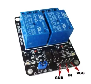
- GND:- It connects to the ground pin of Arduino.
- IN1:- It connects to the digital pin of Arduino to control the first relay.
- IN2:- It connects to Arduino digital pin to controls the second relay (if we using the second relay).
- VCC:- connects to 5V of Arduino.
Main Voltage Connections
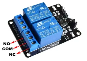
COM:- This is a common pin.
NO (Normally Open):- According to the name Normally Open (NO) pin has no direct connection with the Common pin. If we trigger the relay, NO connects with the COM pin and provided power supply. We connect the lamp or the appliance wire with it.
NC (Normally Closed):- There is a direct connection between the common pin and the normally closed pin, even the relay is off. If we trigger the relay, NC disconnects with COM pin and no supply provided to load.
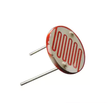
About LDR Sensor
An LDR sensor (Light Dependent Resistor) is a device that is used to detect light. It has a (variable) resistance that changes with the light intensity that falls upon it.
This allows them to be used in light sensing circuits. They are used in many consumer products to determine the intensity of light.
Must See: LDR Sensor with Arduino.
Circuit Diagram for Relay with Arduino
To create this setup, you will need to connect the signal pin of the relay module to one of the digital pins on the Arduino board. The VCC pin should be connected to 5V on the Arduino, and GND should be connected to ground.
Make sure to power your external device separately from a different power source than the Arduino itself for safety reasons. This way, you can avoid potential issues like drawing too much current through the Arduino board.
Code for Relay with Arduino
To control a relay module using an Arduino board, you need to write a simple sketch in the Arduino IDE. The code essentially involves setting up the pin connected to the relay module as an output and then toggling this pin HIGH or LOW to turn the relay on or off.
The working of the below sketch is as when the LDR senses darkness i.e. light intensity below 500 then the relay module gets input from Arduino through pin 9 and there is a connection between the COM and NO pin is established and turns on the light.
When LDR senses light intensity above 500 than the connection between COM and NO pin is broked and the light turns off.
Troubleshooting Common Issues
So, you’ve set up your relay module with Arduino and run into some hiccups along the way. Don’t worry, it happens to the best of us!
- One common issue that may arise is incorrect wiring – double-check all connections to ensure they are secure and in the right place.
- If your relay isn’t switching properly, check for any loose connections or damaged components. Sometimes a simple fix like reseating wires can do the trick.
- Another issue could be related to code errors – review your Arduino sketch carefully for any bugs or typos that might be causing issues with the relay operation. Debugging code is part of the fun in working with electronics!
Practical Applications of Relay Module with Arduino
The practical applications of a relay module with Arduino are vast and diverse, making it an essential component for various projects.
- One common application is home automation, where relays can be used to control lights, fans, or even appliances remotely through the Arduino board.
- In the field of agriculture, relay modules paired with Arduino have been employed in automated irrigation systems that help monitor soil moisture levels and water plants accordingly. This technology not only saves time but also ensures efficient water usage.
- Furthermore, in the realm of robotics, relay modules play a crucial role in controlling motors and actuators based on input signals from sensors connected to the Arduino platform. This enables precise movement and functionality in robotic projects.