ESP8266 WiFi Module
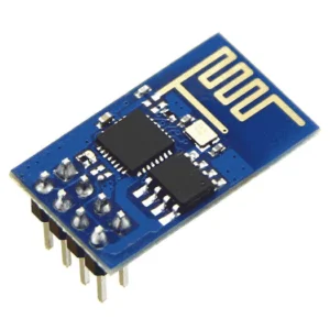
ESP8266 is Wi-Fi enabled system on chip (SoC) module developed by Espressif system. It is mostly used for the development of the Internet of Things (IoT) embedded applications.
The ESP8266 is a low-cost Wi-Fi microchip with full TCP/IP stack and microcontroller capability produced by Shanghai-based Chinese manufacturing company Espressif Systems.
The ESP8266 is capable of either hosting an application or offloading all the Wi-Fi networking functions from another application processor.
Each ESP8266 Wi-Fi module comes pre-programmed with an AT command set firmware, now you can simply hook this up to your Arduino device and get as much Wi-Fi ability as a Wi-Fi Shield offers.
The ESP8266 module is an extremely cost-effective board with a huge, and fastest ever growing, community.
Also See: Upgrade Version NodeMCU and NodeMCU Tutorials

ESP8266 WiFi module Specification
- 2.4 GHz Wi-Fi (802.11 b/g/n, supporting WPA/WPA2).
- General-purpose input/output (16 GPIO).
- Inter-Integrated Circuit (I²C) serial communication protocol.
- Analog-to-digital conversion (10-bit ADC).
- Serial Peripheral Interface (SPI) serial communication protocol.
- I²S (Inter-IC Sound) interfaces with DMA(Direct Memory Access) (sharing pins with GPIO).
- UART (on dedicated pins, plus a transmit-only UART can be enabled on GPIO2).
- Pulse-width modulation (PWM).
It employs a 32-bit RISC CPU (reduced instruction set computer) based on the Tensilica Xtensa L106 running at 80 MHz (or overclocked to 160 MHz).
It has a 64 KB boot ROM, 64 KB instruction RAM, and 96 KB data RAM. External flash memory can be accessed through SPI.
To communicate with the ESP8266 module, the microcontroller needs to use AT commands.
The microcontroller communicates with the ESP8266-01 module using UART (Universal Asynchronous Receiver/Transmitter) having specified Baud rate.
There are many third-party manufacturers that produce different modules based on this chip (ESP8266). So, the module may come with different pin availability options like,
- ESP-01 comes with 8 pins (2 GPIO pins) with PCB (printed circuit board) trace antenna.
- ESP-02 comes with 8 pins, (3 GPIO pins) with a U-FL antenna connector.
- ESP-03 comes with 14 pins, (7 GPIO pins) with Ceramic antenna.
- ESP-04 comes with 14 pins, (7 GPIO pins) and without an antenna.
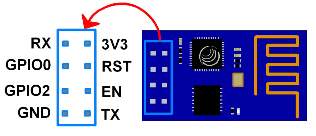
ESP8266 WiFi Module Pinout

- 3V3: – 3.3 V Power Pin.
- GND: – Ground Pin.
- RST: – Active Low Reset Pin.
- EN: – Active High Enable Pin.
- TX: – Serial Transmit Pin of UART.
- RX: – Serial Receive Pin of UART.
- GPIO0 & GPIO2: – General Purpose I/O Pins. Also known as TX/RX pins can be use for Programming the module or for serial I/O purpose.
To program the module using UART, Connect GPIO0 to ground and GPIO2 to VCC or leave it open. To use UART for normal Serial I/O leave both the pins open (neither VCC nor Ground).
How to Use the ESP8266 Module
When it comes to programming the ESP8266, utilizing platforms like Arduino IDE or MicroPython can simplify the process. Take advantage of libraries and resources available online to expedite development.
Experiment with different applications such as IoT projects, home automation systems, or sensor networks to unleash the full potential of the ESP8266 Module.