Introduction to Servo Motor
In this tutorial, we will learn how to control a Servo Motor with an Arduino. Servo motor is an electrical device that can be used to rotate the objects (like a robotic arm) precisely. It is a rotary actuator or the linear actuator which allows precise control of angular or linear position, velocity, and acceleration.
Servo motor has a rotation angle that varies from 0° to 180°.
In this tutorial, we will cover –
- Testing servo motor.
- Servo Motor speed changing.
- Control the Servo Motor speed by the potentiometer.
- Position Control of Servo Motor Shaft by the potentiometer.
How does a Servo Motor work?
Servo motors are fascinating devices that work based on feedback control. Inside a servo motor, there is a regular DC motor paired with a sensor for position feedback. This sensor constantly sends signals to the controller about the current position of the motor shaft. The controller then compares this information to the desired position input by the user.
When the actual and desired positions differ, the controller adjusts the voltage supplied to the motor, causing it to rotate until both positions align perfectly. This continuous process of comparing feedback and making adjustments allows servo motors to maintain precise control over their rotational angle or speed.
Types of Servo Motors and their Applications
When it comes to servo motors, there are various types available to suit different needs. One common type is the DC servo motor, known for its simple design and cost-effectiveness. These motors are often used in robotics, conveyor systems, and automated manufacturing processes.
Another popular type is the AC servo motor, favored for its high precision and speed control capabilities. AC servo motors find applications in CNC machines, printing presses, and industrial automation equipment.
Brushless DC servo motors are known for their efficiency and low maintenance requirements. They are commonly used in aerospace applications, medical devices, and camera gimbals due to their reliable performance.
Components Needed
- Arduino UNO.
- Servo Motor.
- Breadboard.
- Jumper Wires.
Circuit Diagram For Servo Motor with Arduino
The connection between the servo motor and Arduino board determines how smoothly the motor operates.
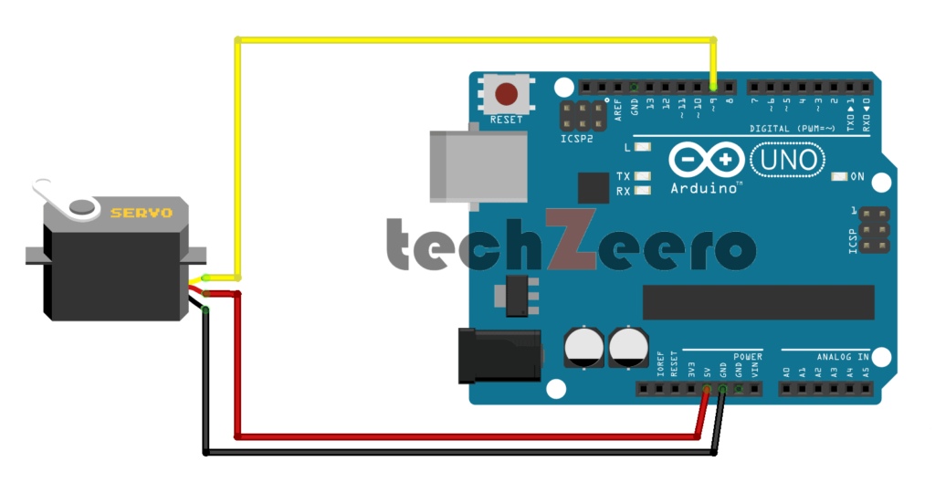
To create this circuit, you will need an Arduino board, a servo motor, jumper wires, and a power source. Start by connecting the ground (GND) pin of the servo motor to one of the GND pins on the Arduino.
Next, connect the power (VCC) pin of the servo to 5V on your board. Then, link the control wire from the servo motor to one of the digital PWM pins on your Arduino.
Pin Connections
| Arduino UNO | Servo Motor |
|---|---|
| Vin 5v | Vcc (Red Wire) |
| GND | GND (Brown Wire) |
| D9 | Control (Orange Wire) |
Code for Servo Motor with Arduino
When it comes to controlling a servo motor with Arduino, writing the code is key. The process involves sending signals to the servo motor to determine its position or speed. By using the Servo library in Arduino IDE, you can easily control the movement of the servo motor.
The code typically includes setting up the servo object, attaching it to a specific pin on your Arduino board, and then specifying commands for positioning or adjusting speed. You can create custom functions to make your servo motor perform specific tasks based on your project requirements.
When the code starts running, the Servo motor rotates from 0° to 180° repeatedly with a pause of half-second from the start position and end position. The servo motor runs with his full speed.
Code for Changing the Servo Motor Speed
When working with a servo motor and Arduino, the ability to change the speed of the motor adds another layer of control to your project. By adjusting the pulse width modulation (PWM) signal sent to the servo, you can effectively alter its speed. This functionality opens up a world of possibilities for creating dynamic and interactive projects.
To implement code for changing the servo motor speed, you will need to modify the PWM values being sent from your Arduino board. By experimenting with different PWM values within a specific range, you can achieve varying speeds for your servo motor. It’s important to test and tweak these values to find the optimal speed control that suits your project requirements.
The below code is to drive the servo motor in slow motion. By changing the delay time in the “for” loop you can increase or decrease the servo motor speed.
Code for Control the speed of Servo using Potentiometer
Controlling the speed of a servo motor using a potentiometer is a fascinating way to achieve precise motion control in your Arduino projects. By incorporating this functionality into your setup, you can dynamically adjust the speed of the servo motor based on real-time input from the potentiometer.
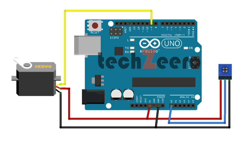
Below is the Circuit diagram to Control the speed of Servo Motor using Potentiometer.
The code for this feature involves mapping the analog readings from the potentiometer to specific speed ranges for the servo motor. This allows you to smoothly transition between different speeds by simply turning the knob of the potentiometer.
Code For Position Control of Servo Shaft
When it comes to controlling the position of a servo motor shaft with Arduino, precision is key.
To achieve this, you will need to write code that sends the desired position value to the servo motor. This value corresponds to the angle at which you want the shaft to be positioned. By adjusting this value in your code, you can control the exact position of the servo motor shaft.
With Arduino’s flexibility and programmability, you have full control over how precisely and efficiently you want your servo motor shaft to move. Experimenting with different values and fine-tuning your code will help you achieve optimal performance in positioning control.
Applications of the Servo Motor in Daily Life
- Servo motors find a wide range of applications across various industries due to their precision and control capabilities. In robotics, servo motors are used in robotic arms to precisely manipulate objects with accuracy.
- They play a crucial role in the aerospace industry for controlling flight surfaces such as flaps and rudders on aircraft.
- In the field of automation, servo motors are utilized in CNC machines for precise positioning and movement of cutting tools. They are also commonly found in 3D printers to control the extruder and build platform movements accurately.
- Servo motors are essential components in camera gimbals, ensuring smooth and stable footage during photography or videography.
- Moreover, servo motors are employed in the automotive industry for tasks like controlling throttle valves and steering systems with high precision.
Troubleshooting Common Issues
Troubleshooting common issues with a servo motor connected to an Arduino can sometimes be a bit tricky.
- One of the most frequent problems is incorrect wiring, so always double-check your connections. If your servo motor is not moving as expected, it could be due to insufficient power supply – ensure that the power source can handle the load.
- Another issue could stem from using incompatible code or libraries – make sure they are compatible with both the servo motor and Arduino board you are using.
- Noise interference from other electronics nearby might also cause erratic behavior in the servo motor, so try isolating it if possible.
- Calibrating the servo motor correctly is crucial for smooth operation; improper calibration might lead to inaccuracies in positioning.
If all else fails, consider testing components individually to identify any faulty parts causing malfunctions.