In this tutorial, we learn how to interfacing RFID with an Arduino. An RFID Sensor, which is a Radio Frequency Identification Reader, gathers data from a card with an RFID tag.
An RFID reader reads RFID tags. It transfers data from the card tag to an RFID reader using radio waves.
RFID technology identifies the presence of objects wirelessly.
Similar to barcode technology, RFID reads the card tag to identify objects and persons. This surpasses bar code technology because bar codes can sometimes become damaged or unreadable.
This RFID module is a 125KHz card reader mini-module which is design to read ing code from the 125KHz card tag.
Companies mainly use it to access authorized employees, attendance systems, and personal identification.
Must see:
Components of an RFID System
RFID systems consist of three main components: the RFID tag, the reader, and the software. The RFID tag is a small device that contains a unique identifier. Tags come in various forms, including cards, key fobs, and stickers. The reader is the device responsible for sending and receiving signals to communicate with the tags.
The reader emits radio waves to power up the RFID tags within its range. Once powered up, the tag responds by transmitting its data back to the reader. This data can include information like product details or access permissions.
Software plays a crucial role in managing and interpreting the data collected by RFID readers. It enables users to track assets, monitor inventory levels, and enhance security measures through access control systems.
Together, these components create a seamless system that offers efficiency and convenience across various industries such as retail, logistics, healthcare, and more.
RC522 RFID Pinout
RC522 RFID Sensor has 8 pins.
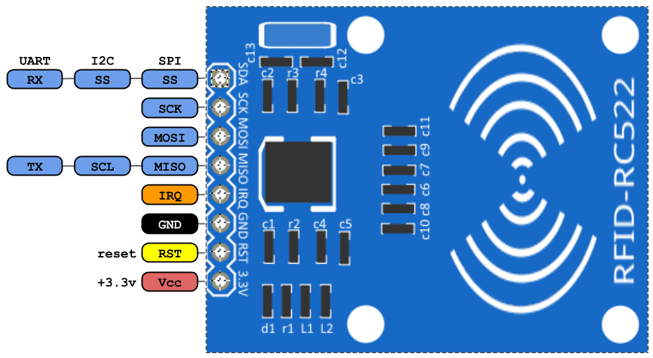
- VCC (3.3v):- Connect the VCC pin to the 3.3V pin of the Arduino. Connecting it to the 5v Arduino pin can destroy the RFID module.
- RST:- This pin is for resetting the module.
- GND:- This pin connects to the GND pin of Arduino.
- IRQ:- This is blocking or interrupt pin that can alert the microcontroller when it comes around the RFID tag.
- MISO/SCL/TX:- This pin is Master-In-Slave-Out. It acts as serial data output and connects to the Arduino RX pin.
- MOSI:- Master-Out-Slave-In pin is SPI input to the RC522 module.
- SCK:– Serial Clock is accepting clock pulses provided by Arduino.
- SS / SDA / Rx:- When the SPI interface is enabled it acts like Signal input when the I2C interface is enabled it acts like Serial data and acts as Serial data input when the UART interface is enabled. This pin usually connects to the Arduino TX pin.
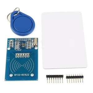
Components Needed
- Arduino UNO.
- RC522 RFID.
- Jumper Wires.
- Breadboard.
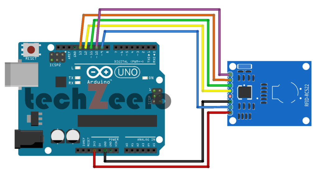
Circuit Diagram For Interfacing RFID with Arduino
n the circuit diagram for this integration, you’ll typically see the RC522 RFID module connected to specific pins on the Arduino board. These connections allow for data exchange between the RFID reader and Arduino microcontroller.
The wiring configuration in the diagram ensures that power, ground, and communication lines are properly established between the RFID module and Arduino. Each connection plays a vital role in enabling seamless interaction between the two components.
Code for Interfacing RFID with Arduino
You need to install the IR library. Now go to Sketch > Include Library > Manage Libraries and search for MFRC522 by shirriff.
OR just download from https://github.com/miguelbalboa/rfid and Add .Zip Library.
This code also available in the library which you can get from File > Examples > MFRC522 > DumpInfo. Upload this code and open Serial Monitor and scan RFID Card or Keychain. By using this code you get more information about RFID Reader and cards.
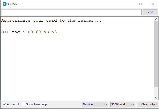
Output
Code For Access Card
The programming involves setting up rules in the Arduino code that determine which RFID tags are granted access and which are denied. By assigning unique identifiers to each access card, you can control who can enter a certain area or activate a particular function.
From the first code, we get an RFID card tag value. Put those output card tag value in the below code in the function:
if (content.substring(1) == "F0 60 AB A3") //Change this UID
Now after changing the tag value, upload the code.
Applications of RFID-Arduino Integration
RFID technology integrated with Arduino opens up a myriad of applications across various industries.
- One common use is in access control systems, where RFID cards are used to grant entry to secure areas or buildings. This integration ensures seamless and secure access for authorized personnel only.
- Inventory management is another vital application where RFID tags attached to products can be scanned by an Arduino reader for real-time tracking of stock levels. This simplifies the inventory process, reduces human error, and improves overall efficiency.
- In the healthcare sector, RFID-Arduino integration can enhance patient safety by tracking medical equipment and ensuring that the right tools are available when needed. This helps streamline operations and improve patient care significantly.
- Moreover, in retail environments, this integration enables efficient product authentication and anti-theft measures through RFID-tagged items. It enhances customer experience while reducing losses due to theft or counterfeit products.
Tips for Troubleshooting Common Issues
Encountering issues when interfacing RFID with Arduino can be frustrating but fear not, as there are some common tips to help you troubleshoot and resolve them efficiently.
- Double-check all the connections between the RC522 RFID module and Arduino. Loose or incorrect wiring can often be the culprit behind communication errors.
- Ensure that your power supply is stable and capable of providing enough current for both components to function properly. Inadequate power supply can lead to inconsistent readings or even failure in reading RFID tags.
- If you’re still facing problems, try adjusting the antenna position on the RC522 module. Sometimes a small tweak in its placement can significantly improve signal reception and data transfer reliability.
- It’s also recommended to update your Arduino IDE and libraries regularly to avoid compatibility issues between different software versions. Keeping everything up-to-date can prevent potential software conflicts that may arise during operation.