Introduction to Thermistor and Arduino
In this blog post, we learn how to interfacing Thermistor with an Arduino. We also get the temperature readings from Thermistor and display them on LCD Display.
Whether you’re a beginner or an experienced maker, understanding how thermistors work and integrating them into your projects opens up a whole new realm of possibilities. So, grab your soldering iron and let’s get started on this exciting journey of connecting thermistors with Arduino!
A thermistor is also known as a thermal resistor that is used to sensing temperature like cold and heat around us. The thermistor is a resistor whose resistor is changed according to change in temperature.
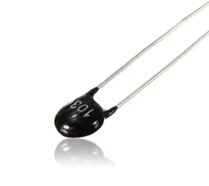
Thermistors are cheap, reliable and respond quickly. They are mainly used for low-temperature range but not for high temperatures.
Thermistors are mainly used in home appliances, for circuit protections, refrigerator, etc.
Types of Thermistors
Thermistors come in various types, each designed for specific applications. One common type is the NTC thermistor, which stands for Negative Temperature Coefficient. As the temperature increases, the resistance of an NTC thermistor decreases.
On the other hand, there are also PTC thermistors, or Positive Temperature Coefficient thermistors. Unlike NTCs, as temperatures rise, so does the resistance of a PTC thermistor. This unique characteristic makes them useful in different scenarios compared to NTCs.
Another type is precision thermistors known for their high accuracy and stable performance over a wide temperature range. These are commonly used in industries where precise temperature control is crucial.
How a Thermistor Works
Thermistors are fascinating devices that change their resistance with temperature. Unlike traditional resistors, their resistance decreases as the temperature increases, and vice versa. This unique characteristic makes them ideal for various applications in temperature sensing and control systems.
The working principle of a thermistor is based on the change in the number of charge carriers within its semiconductor material as the temperature changes. When heated, more charge carriers become available, reducing the resistance. Conversely, when cooled, fewer charge carriers are available, increasing the resistance.
This nonlinear relationship between resistance and temperature allows thermistors to provide precise and accurate measurements across a wide range of temperatures.
Components Needed
- Arduino UNO.
- Thermistor.
- 1 KΩ Resistor.
- Jumper Wires.
- Breadboard.
- LCD 16×2 Display.
- Potentiometer.
Circuit Diagram For Thermistor with Arduino
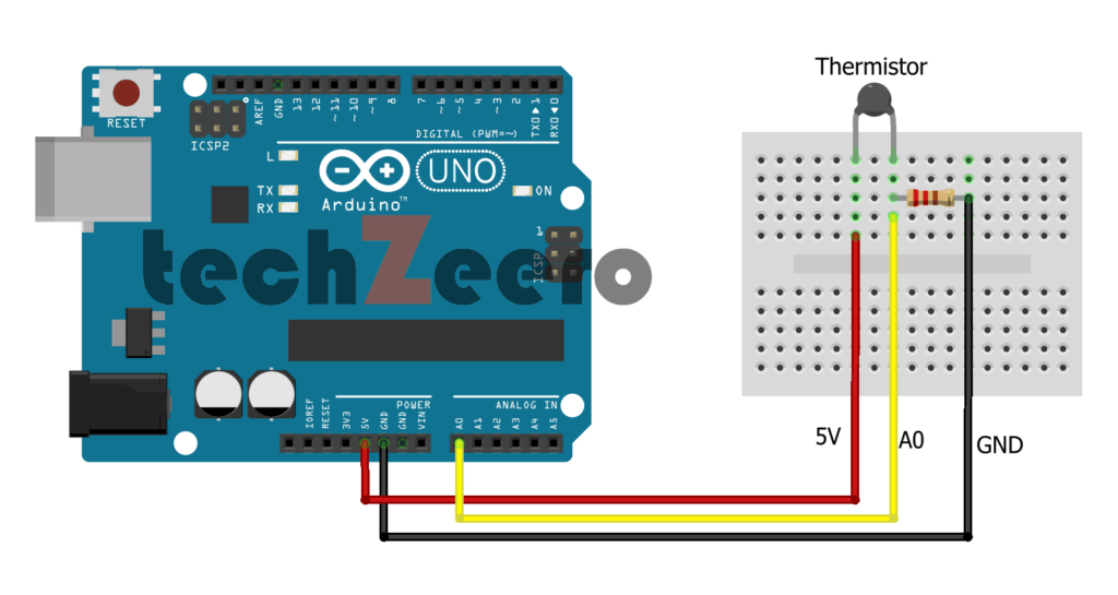
The circuit diagram typically involves connecting the thermistor to one of the analog pins on the Arduino board.
To begin, gather your materials including an NTC or PTC thermistor, an Arduino board, a breadboard, and jumper wires. Next, carefully place the components on the breadboard according to the schematic.
The connection usually consists of wiring one leg of the thermistor to 5V on the Arduino and connecting its other leg to both an analog pin and a resistor that leads back to ground. This setup allows you to measure changes in resistance as temperature fluctuates.
Code for Thermistor with Arduino
Firstly we need to define the analog pin where the thermistor is connected on the Arduino board. This will be used for reading voltage variations based on temperature changes detected by the thermistor.
Next, you’ll write a function that converts these voltage readings into corresponding temperatures using Steinhart-Hart equation or other relevant formulas depending on your specific thermistor type.
You can then incorporate this function within your main loop to continuously monitor and display temperature readings in real-time through serial communication or any output device connected to your Arduino setup.
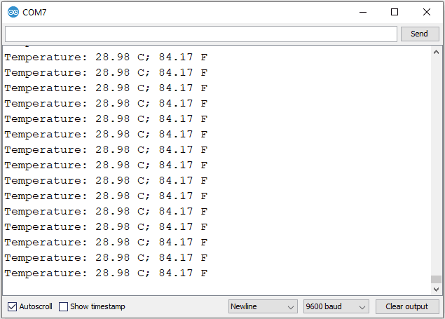
Upload the below code and open the serial monitor to view temperature readings.
Output
Now we will display the thermistor temperature readings on an LCD Display. So we connect an LCD 16×2 display and thermistor with Arduino.
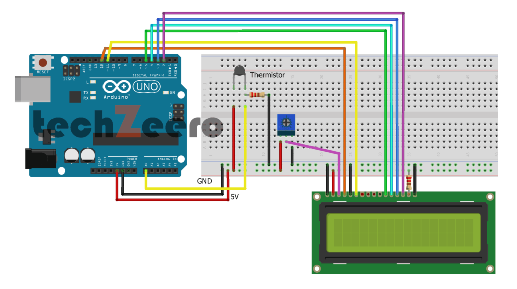
Circuit Diagram For Thermistor and LCD Display with Arduino
Lets creating a circuit diagram for interfacing a thermistor and an LCD display with Arduino. The first step is to connect the thermistor in a voltage divider configuration, where it acts as one of the resistors along with another fixed resistor. This setup allows us to measure changes in resistance based on temperature variations.
Next, we incorporate the LCD display by connecting it to the Arduino board using jumper wires. The display will show real-time temperature readings captured by the thermistor. By combining these components, we can visualize temperature data in a user-friendly format.
Ensure you follow the correct pin connections as per your specific thermistor and LCD model. Double-check your wiring before powering up the circuit to avoid any potential issues.
Must to see:-
Code For Thermistor and LCD Display with Arduino
The code will involve setting up pins for both the thermistor sensor and the LCD display, as well as initializing necessary libraries for communication. Additionally, we’ll be implementing conditional statements to ensure accurate readings are displayed based on temperature variations.
By converting the analog signal into temperature values using specific calculations, we can then send this information to be displayed on the LCD screen.
Upload the below code and view the output on the LCD Display.
Testing and Troubleshooting
Once you have connected the thermistor to your Arduino and uploaded the code, it’s time to test if everything is working correctly.
- Start by monitoring the serial monitor for temperature readings. If you’re not getting any values or inaccurate readings, double-check your connections and code.
- Ensure that the thermistor is securely in place and properly calibrated. Test different temperature scenarios to see how the thermistor responds. If there are discrepancies, recalibrate or adjust your code accordingly.
- If troubleshooting becomes necessary, consider checking for any loose wires or damaged components. Verify that all components are functioning as they should be. Sometimes a simple oversight can lead to issues with readings.
Applications and Benefits of Using a Thermistor with Arduino
Thermistors interfaced with Arduino boards have a wide range of applications across various industries.
- One common use is in temperature monitoring systems for environmental control in buildings, ensuring optimal comfort levels while saving energy.
- In the healthcare sector, thermistors are vital components in medical devices like thermometers and incubators, enabling precise temperature measurements.
- Another key application is in industrial automation to monitor equipment temperatures and prevent overheating or malfunctions. By integrating thermistors with Arduino, businesses can enhance operational efficiency and reduce downtime significantly.
- Additionally, these sensors play a crucial role in automotive applications, such as engine temperature monitoring and climate control systems.
Uses of Thermistor
- Use for circuit protection.
- Uses in home appliances like refrigerator, ovens.
- Digital thermometers.
- Rechargeable batteries.