Introduction to Flame Sensors
Are you looking to add an extra layer of safety and security to your surroundings? Imagine having a reliable system in place that can detect the smallest hint of danger before it escalates. Well, look no further! In this blog post, we will delve into the fascinating world of flame sensor with Arduino for fire detection.
In this blog, we learn how to interface a flame sensor with Arduino, and How to detect fire/flames using a flame sensor.
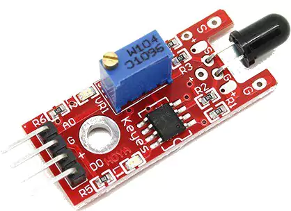
A flame sensor is a device used to detect a fire. It is the most sensitive that can easily detect a fire and activate a fire alarm.
The detection range of a flame sensor is the wavelength in 760 nm to 1100 nm range of light source.
High temperatures can damage the sensor so we should place it at some distance. The detection distance is up to 100 cm.
Its output is a digital or analog signal. It can be used as a flame alarm or in the fire fighting robots.
It works by detecting infrared radiation emitted from the fire. The detector detects this radiation and converts it into the analog and digital signals for the microcontroller to process.
How do Flame Sensors Work?
Flame sensors are essential components in fire detection systems, designed to detect the presence of flames by monitoring infrared light emitted by them. When a flame is present, it emits an IR signature that the sensor can detect.
The sensor consists of a photodiode and an amplifier circuit that converts the received IR radiation into an electrical signal. This signal is then processed to determine if there is a flame nearby.
Once the flame sensor detects a significant level of infrared radiation, it triggers an alarm or activates other safety measures to alert individuals of potential fire hazards.
Note: Since the flame sensor works on the principle of infrared detection, any other infrared source like your remote control or any other source can trigger the sensor.
Flame Sensor Specifications
- Board Size: 15.25 mm x 33 mm x 12.7 mm
- Operating voltage: 3.3 or 5V DC
- Range: 10 cm to 80 cm
- The angle of Detection: 60 degrees
- Weight: 20 gm.
Types of Flame Sensors
When it comes to flame sensors, there are a few different types that serve unique purposes in fire detection systems.
One common type is the Infrared (IR) Flame Sensor, which works by detecting the infrared radiation emitted by flames. This sensor is great for detecting fires in environments with high background light.
Another type is the Ultraviolet (UV) Flame Sensor, which detects the UV light emitted by flames. These sensors are sensitive and quick to respond, making them ideal for fast-acting fire detection systems.
Additionally, there are Combination Flame Sensors that utilize both IR and UV technologies for enhanced accuracy and reliability in fire detection.
Components Needed
- Arduino Board
- Flame Sensor
- Jumper Wires
- 1 x Breadboard
- Buzzer
Pin Connection of Flame Sensor
| Flame Sensor | Arduino Pins |
|---|---|
| Vcc +5v | 5v |
| GND | GND |
| A0 | A0 |
| D0 | D2 |
We will test the flame sensor using both pins digital and analog.
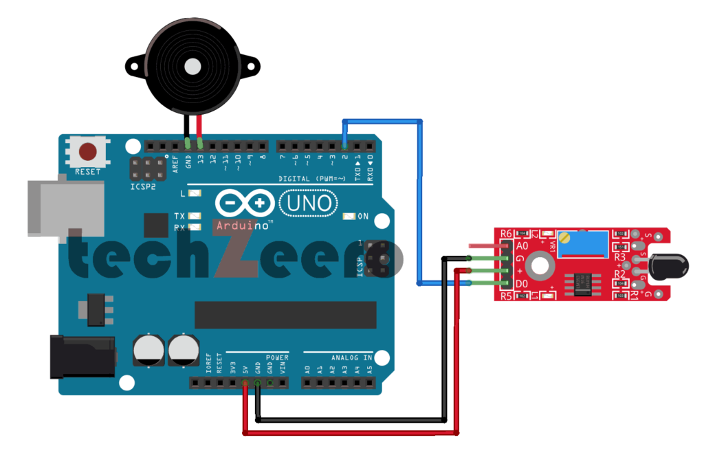
Circuit Diagram of Flame Sensor with Arduino Using Digital Pin
Connect the VCC pin of the flame sensor module to 5V on the Arduino board. Then, link GND from the sensor to GND on the board. Next, connect DO (digital output) from the sensor to any digital pin on Arduino – let’s say Pin 2.
And connect a buzzer to Pin 13 of Arduino.
After setting up these connections, upload code to your Arduino that reads data from Pin 2 where your flame sensor is connected. This code will enable you to detect flames based on threshold values set in your program.
Code for Flame Sensor Using Digital Pin
Begin by defining the digital pin you are connecting your flame sensor to on the Arduino board. This establishes communication between the sensor and the microcontroller.
Next, you will need to set up your Arduino sketch by initializing the digital pin as an input where the flame sensor signal will be received. You can then proceed to read this input using simple conditional statements in your code.
Based on these readings, you can program specific actions or responses such as activating an alarm or sending a notification when flames are detected.
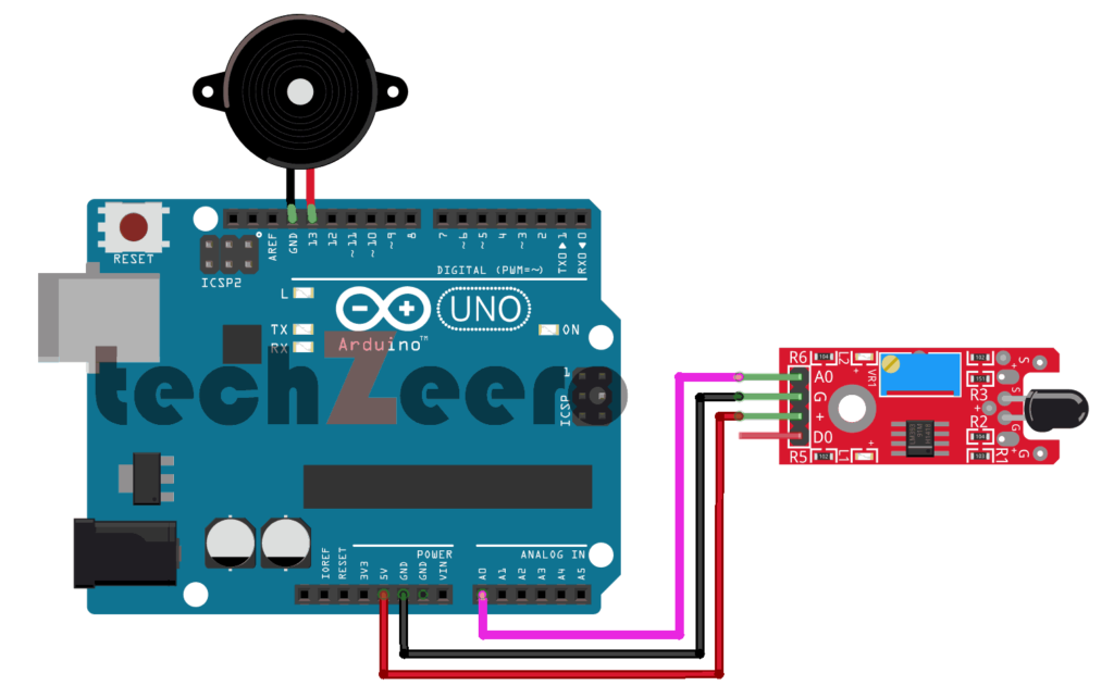
Circuit Diagram of Flame Sensor with Arduino Using Analog Pin
Now, let’s delve into the circuit diagram of using a flame sensor with an Arduino board via an analog pin. This method allows for more precise detection of fire by measuring varying analog signals.
To start, connect the VCC and GND pins of the flame sensor to 5V and GND on the Arduino respectively. Then, link the A0 pin on the flame sensor to any available analog pin on your Arduino board.
Next, upload a code that reads the analog input from the flame sensor connected to the selected analog pin.
Code for Flame Sensor Using Analog Pin
By utilizing the analog input capability of Arduino boards, we can achieve more precise detection and analysis of flame signals.
To begin, connect the flame sensor to the analog pin on your Arduino board following the circuit diagram provided. Next, upload the code specifically designed for reading analog data from the sensor. This code allows you to capture varying voltage levels corresponding to different intensities of flames detected by the sensor.
Once uploaded, monitor the serial monitor in your Arduino IDE to observe real-time data readings from the flame sensor through the analog pin. You can adjust sensitivity thresholds and trigger responses based on these readings to customize your fire detection system accordingly.
Testing and Troubleshooting
When testing your flame sensor with Arduino, it’s essential to ensure all connections are secure and the components are functioning correctly. Start by uploading the code to your Arduino board and monitor the serial output for any readings from the flame sensor.
- If you encounter issues with detecting flames, double-check the wiring connections to make sure they are properly connected. Sometimes a loose connection can cause unreliable readings or no response at all from the sensor.
- To troubleshoot any potential problems, try adjusting the sensitivity of the flame sensor using potentiometers if available on your module. This can help fine-tune its detection capabilities based on environmental conditions or different types of flames.
- Since the flame sensor works on the principle of infrared detection, any other infrared source like your remote control or any other source can trigger the sensor.
Potential Applications for Fire Detection using Flame Sensors
Flame sensors with Arduino offer a wide range of potential applications for fire detection beyond just traditional smoke alarms.
- One key area where flame sensors shine is in industrial settings, where they can quickly detect fires in factories or warehouses before they escalate.
- In commercial buildings, flame sensors can provide an added layer of safety by detecting fires early on and alerting occupants to evacuate promptly.
- This technology is also increasingly being integrated into smart homes to enhance fire safety measures and protect families from potential disasters.
- Moreover, flame sensors are utilized in vehicles to prevent engine fires by sensing any flames that may occur within the vehicle’s engine compartment.
- Additionally, these sensors have found their way into public spaces like airports and train stations to bolster existing fire detection systems.