Introduction to Soil Moisture Sensor
Are your plants getting just the right amount of hydration they need? Or are you unknowingly drowning them in waterlogged soil? Enter the game-changer: Soil Moisture Sensor with Arduino! These nifty devices offer a solution to all your plant-watering woes by providing real-time data on soil moisture levels.
In this blog post, we’ll delve into the process of connecting the Soil Moisture Sensor with Arduino, along with showcasing how to exhibit the sensor’s readings on an LCD 16×2 display.
The Soil Moisture Sensor offers both digital and analog output options. Therefore, throughout this article, we’ll explore interfacing the sensor in both modes.
Primarily, the Soil Moisture Sensor serves the purpose of gauging the water content, specifically the volumetric water content, present in the soil.
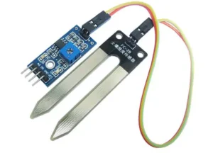
This sensor features two legs designed to measure the volumetric water content effectively.
As current flows through the soil, its moisture level affects the amount of current passing through. Consequently, higher moisture levels in the soil lead to increased current flow and reduced resistance. As a result, the sensor provides readings indicative of higher moisture levels.
Types of Soil Moisture Sensors
When it comes to soil moisture sensors, there are a few different types available on the market.
- One common type is the resistive sensor, which measures the resistance between two electrodes in the soil.
- Another type is the capacitive sensor, which works by measuring changes in capacitance as soil moisture levels fluctuate.
- Tensiometers are another type of soil moisture sensor that measure water tension in the soil. They operate by gauging how much force is needed to extract water from the soil.
- Time domain reflectometry (TDR) sensors use electromagnetic waves to determine soil moisture content based on how quickly the waves travel through the soil.
How Does a Soil Moisture Sensor Work?
Soil moisture sensors work by measuring the amount of water content in the soil. These sensors typically consist of two electrodes that measure the electrical conductivity of the soil. When the soil is dry, it has a higher resistance to electricity flow compared to when it’s wet.
The sensor sends an electrical signal through the soil, and based on how easily this signal travels between the electrodes, it determines the moisture level. The more conductive (wetter) the soil is, the easier it is for electricity to pass through.
By analyzing these conductivity levels, soil moisture sensors can provide valuable data on whether plants need watering or if they are receiving too much water. This information helps gardeners and farmers optimize their irrigation practices and ensure healthy plant growth.
Components Needed
- Arduino.
- Soil Moisture Sensor.
- LCD Display 16×2.
- Jumper Wires.
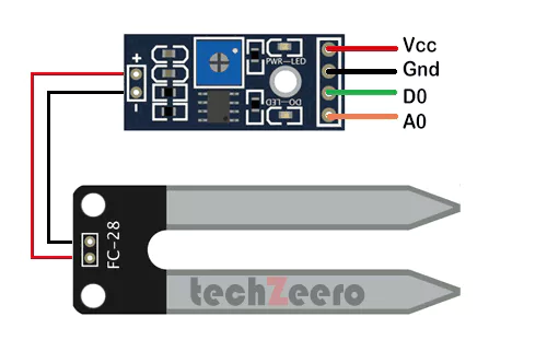
Soil Moisture Sensor Pinout
Soil Moisture sensor FC-28 has four pins. It attached to the LM393 comparator which contains a potentiometer.
- The VCC pin is connected to the 5V output on the Arduino board to power the sensor.
- The GND pin is linked to the ground (GND) on the Arduino for electrical reference.
- The D0 pin provides digital output, it outputs a high or low signal depending on preset thresholds.
- The A0 pin provides analog output, it gives a variable voltage reading corresponding to soil moisture levels.
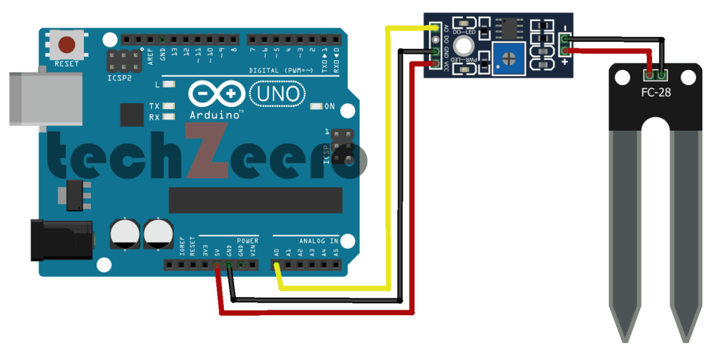
Analog Mode – Interfacing Soil Moisture Sensor with Arduino using Analog Pin
The analog mode allows for continuous readings that reflect the varying levels of moisture in the soil.
By connecting the sensor to an analog pin on your Arduino board, you enable it to convert the input voltage from the sensor into a digital value that can be interpreted by the microcontroller. This setup gives you real-time data on soil moisture levels, crucial for efficient plant care.
In this mode, we are using the analog pin of the sensor to get output. The sensor gives analog values from 0 – 1023 and moisture are measured in percentage, so we will map these values from 0-100 by using map function in code.
Circuit Diagram
Code – Analog Output
To start, you’ll need to connect the sensor to an analog pin on your Arduino. This will allow you to read the varying voltage levels from the sensor that correspond to different levels of soil moisture.
Next, you can write a simple code in the Arduino IDE that reads these analog values and converts them into meaningful data. By mapping these values, you can get accurate readings of how moist or dry your soil is.
Remember to calibrate your sensor and adjust the threshold values in your code based on the specific requirements of your project. This will ensure precise results from your soil moisture sensor when using analog output mode.
Open serial monitor to view the sensor values.
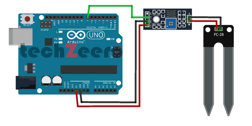
Digital Mode – Interfacing Soil Moisture Sensor with Arduino using Digital Pin
This method provides binary data, making it easier to interpret the moisture levels in the soil accurately. By utilizing the digital output of the sensor, you can set specific threshold values to trigger actions based on moisture conditions.
To interface the sensor in Digital Mode, connect its DO pin to any digital pin on the Arduino board. This configuration enables direct communication between the sensor and Arduino without analog conversion. Additionally, adjusting the sensitivity of the sensor can help fine-tune its response to different moisture levels in the soil.
Circuit Diagram
Code – Digital Output
To set up the code for digital output, you’ll need to define the input and output pins in your sketch. This allows the Arduino to communicate with the sensor and interpret its readings accurately.
Using conditional statements like if/else loops in your code will help you determine specific thresholds of moisture levels that trigger actions or alerts. This functionality adds a layer of customization to suit different application needs.
Upload the code to the Arduino board. When the value of the sensor is high, the inbuild led will on.
Display Soil Moisture Sensor Reading on LCD 16×2
Wondering how to display soil moisture sensor readings on an LCD 16×2 screen using Arduino? It’s simpler than you think! By connecting the soil moisture sensor and the LCD screen to your Arduino board, you can easily showcase real-time data.
Start by wiring the components according to their pinouts. Utilize analog or digital mode depending on your setup. For analog output, link the sensor’s signal pin to an analog pin on the Arduino board. Then, with a few lines of code, read and map the sensor values for accurate readings.
Incorporating a digital approach involves connecting the sensor’s output to a digital pin on the board. Adjust thresholds in your code for different levels of soil moisture detection.
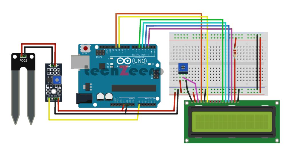
Now we are going to display the soil moisture sensor readings on an LCD 16×2 display. We use the analog pin output of the soil moisture sensor.
Read More about LCD 16×2:
Circuit Diagram
Code for Soil Moisture with LCD 16×2
To display soil moisture sensor readings on an LCD 16×2 screen using Arduino, you’ll need to write a code that reads the analog output from the sensor. Begin by initializing the sensor pin and defining variables for sensor values. Next, set up the LCD library and define pins for connection.
In the code, read the analog value from the sensor using Arduino’s analogRead() function. Convert this value to a percentage representing soil moisture levels based on your calibration. Then, print this value on the LCD screen using lcd.print(). You can also add additional information like units or messages for clarity.
Practical Applications of Soil Moisture Sensors
Soil moisture sensors have a wide range of practical applications beyond just monitoring plant hydration levels.
- One common use is in agriculture, where these sensors help farmers optimize irrigation schedules and conserve water by delivering the right amount at the right time.
- In landscaping, soil moisture sensors can be integrated into automated systems to ensure lawns and gardens are adequately watered without waste. This not only saves water but also promotes healthier plants and reduces maintenance costs.
- For researchers studying ecosystems or climate change, soil moisture sensors provide valuable data on soil health and water availability. By collecting precise measurements over time, they can better understand how environmental factors impact different habitats.
- In urban settings, these sensors play a crucial role in managing stormwater runoff by detecting saturation levels in the ground. This helps prevent flooding and protects infrastructure from potential damage caused by excess water accumulation.
Troubleshooting Common Issues for Soil Moisture Sensor with Arduino
If you encounter issues with your soil moisture sensor while using it with Arduino, fret not!
- One common problem could be incorrect wiring. Double-check the connections to ensure they are properly set up according to the pinout diagram.
- Another issue might be related to code errors. Check for any mistakes in your Arduino sketch, such as incorrect variable names or missing libraries. Debugging these errors can help resolve sensor reading inconsistencies.
- Calibration problems can also arise if the sensor is not adjusted correctly for the type of soil you are monitoring. Make sure to calibrate your sensor based on the specific soil conditions where it is being used.
- Additionally, environmental factors like excess water or interference from other electronic devices nearby can affect sensor readings. Ensure that the environment is stable and free from any external disturbances for accurate results.