Introduction to Tilt Sensor and Arduino
In this blog, we will learn how to interface a tilt sensor with Arduino. A tilt sensor is used to detect a movement, tilted or shaken of an object.
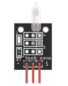
The tilt sensor is commonly a ball bearing in a box with contacts at one end. When the box is tilted the ball rolls away from the contact and the connection is a loss.
On the other hand, when the box is tilted to roll the other way the ball touches the contact and completes the circuit.
The tilt sensor is sensitive to small movement of around 5 to 10 degrees when oriented with the ball just touching the contacts.
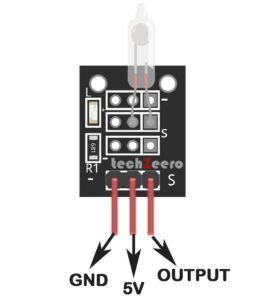
Tilt Sensor Pinout
The sensor typically has three pins: VCC, GND, and OUT.
The VCC pin is where you connect the positive voltage supply, usually 5V from the Arduino board. Meanwhile, the GND pin is where you attach the ground connection to complete the circuit.
The OUT pin is where you receive the digital signal output based on tilt detection. This pin will change its state when the sensor tilts beyond a certain threshold angle.
Components Needed
- Arduino.
- Tilt Sensor.
- LEDs.
- Breadboard.
- Jumper Wires.
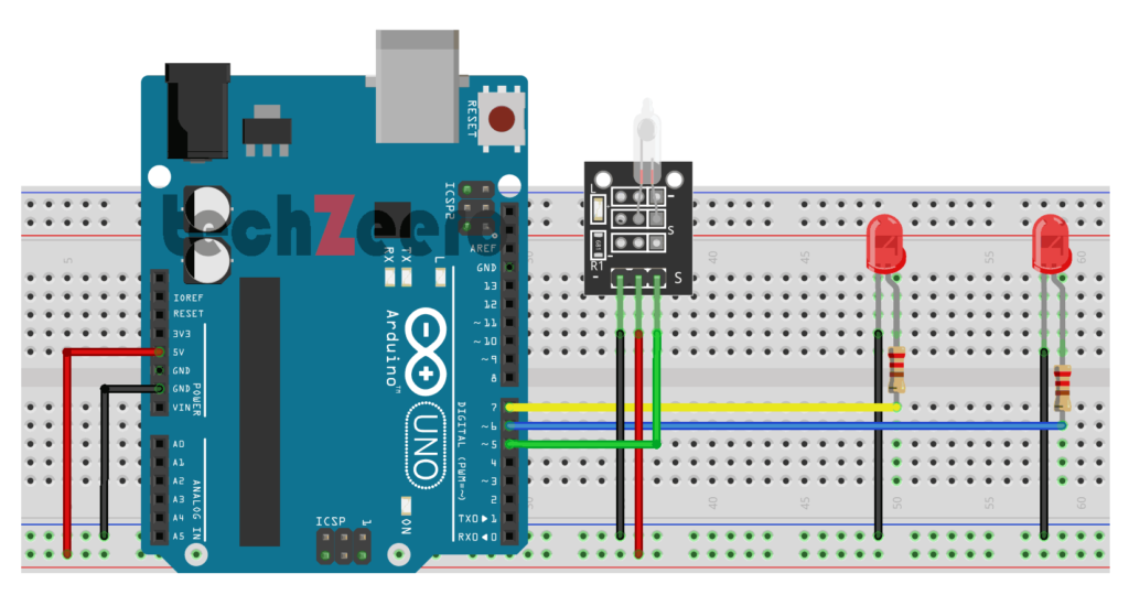
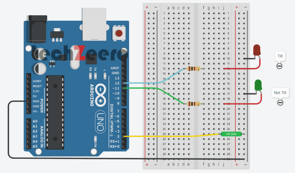
Circuit Diagram for Tilt Sensor with Arduino
The diagram illustrates how to connect the components for accurate readings and functionality.
To begin, locate the pinout of the tilt sensor and identify its key pins: VCC, GND, and OUT. These pins play vital roles in connecting the sensor to the Arduino board effectively.
Next, carefully follow the circuit diagram instructions provided to ensure proper wiring of the tilt sensor with Arduino. It’s essential to double-check all connections to avoid any potential issues during testing.
Code for Tilt Sensor with Arduino
When working with a tilt sensor and Arduino, the code plays a crucial role in capturing and interpreting the sensor data. The programming logic you implement will determine how the Arduino responds to changes in tilt angle.
To start, make sure your code includes defining the necessary pins for both the tilt sensor and any additional components connected to the Arduino. This step ensures that the microcontroller can communicate effectively with all parts of the circuit.
Next, set up conditional statements within your code to detect specific tilt angles or movements. By establishing thresholds for triggering actions based on sensor readings, you can customize how your project interacts with its environment.
The code uses a switch that closes a circuit when tilted, called a tilt sensor.
The below code will switch on the LED attached to pin 11 when the tilt sensors are tilted one way, and the LED connected to pin 12 will switch on when it is tilted the other way:
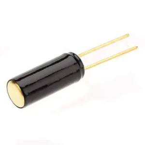
Use of only Tilt Sensor Switch with Arduino
The tilt sensor switch is the main part of the whole sensor module. By connecting the tilt sensor switch to the Arduino, you can create a simple yet effective project that detects changes in orientation. This means that as soon as the sensor is tilted or moved, it sends a signal to the Arduino, triggering various actions based on your programming.
The following figure is of the tilt sensor switch.
Circuit Diagram for Tilt Switch
The circuit diagram for connecting a tilt switch to an Arduino board is relatively simple and requires minimal components.
To start, connect one leg of the tilt switch to 5V on the Arduino board and the other leg to a digital pin (e.g., Pin 2). Ground should be connected directly to another terminal of the tilt switch.
Also connect 2 led’s which show the state of tilt switch sensor.
Code for Tilt Switch
The code for the tilt switch involves setting up digital pins to read the sensor’s state and then triggering actions based on its position.
To start, you will need to declare variables to store pin numbers and create setup functions to initialize communication with the tilt switch. Next, write a loop function that continuously checks the sensor’s status using digitalRead().
Based on whether the sensor is tilted or not, you can program your Arduino board to execute specific tasks like turning on an LED light. Don’t forget to add delays in your code to ensure smooth operation and prevent rapid toggling between states.
Output
The output of a tilt sensor can vary based on its orientation – horizontal or vertical. By utilizing Arduino, we can interpret this output in real-time to trigger specific actions or responses.
The output from the tilt sensor is typically in the form of a digital signal that changes state when tilting occurs. This change in state can be used to control LEDs.
Detect Change in the State of Sensor
To detect changes effectively, you’ll need to continuously read the sensor’s data using the Arduino. This involves establishing a baseline reading when the sensor is in its neutral position and then comparing subsequent readings to determine any deviations.
To determine if something is being shaken, we need to check how long it’s been since the state of the tilt sensor changed.
If it hasn’t changed for a time you consider significant, the object is not shaking. Changing the orientation of the tilt sensor will change how vigorous the shaking need to be to trigger it.
Remove the LED from Pin 11.
Code for Check the Sensor state
In this section, we will write a simple Arduino sketch that reads the output of the tilt sensor and displays whether it is tilted or not on the serial monitor.
We need to declare a variable to store the reading from the tilt sensor. We can use a digital input pin on the Arduino board to read this value.
The following code turns on an LED when the sensor is shaken.
Troubleshooting Common Issues
Having trouble with your tilt sensor and Arduino project? Don’t fret, troubleshooting common issues can help you get back on track.
- First things first, double-check all your connections. Ensure that everything is properly wired according to the circuit diagram. Loose connections or incorrect wiring can often lead to malfunctions.
- If your tilt sensor is not responding as expected, try adjusting its sensitivity. Sometimes a slight calibration can make a big difference in detecting tilts accurately.
- Another common issue could be related to the code. Make sure there are no typos or errors in the programming that could be causing unexpected behavior from the tilt sensor.
- If none of these steps resolve the problem, consider testing each component individually to pinpoint where the issue lies. It could be a faulty sensor, Arduino board, or even a damaged wire causing the issue.
Applications of Tilt Sensor with Arduino
Interested in exploring the diverse applications of tilt sensors with Arduino? You’ll be fascinated by the versatility this combination offers across various fields.
- In industries, tilt sensors integrated with Arduino can monitor equipment orientation for maintenance and safety purposes.
- In robotics, these sensors are used to detect movement changes and adjust robot navigation accordingly.
- Additionally, tilt sensors find their place in gaming controllers where tilting gestures translate into on-screen actions.
- Moreover, in automotive applications, they assist in vehicle stability control systems by sensing incline angles.
- Environmental monitoring stations utilize them for tracking environmental data based on sensor positioning.
- Furthermore, tilt sensors play a crucial role in aerospace technology for aircraft instrumentation and determining spatial orientation during flight maneuvers.