Introduction of Keypad with Arduino
In this blog, we are learning how to set up a keypad matrix with an Arduino. We use both type keypads i.e 4×3 keypad and 4×4 keypad. The output is shown in the serial monitor.
Keypads are used to giving outputs like passwords, menu navigation, gaming control, etc.
A 4×4 keypad has 4 rows and 4 columns whereas 4×3 keypad has 4 rows and 3 columns.
Must See:
Components Needed
- Arduino
- Keypad Matrix
- Jumper Wires
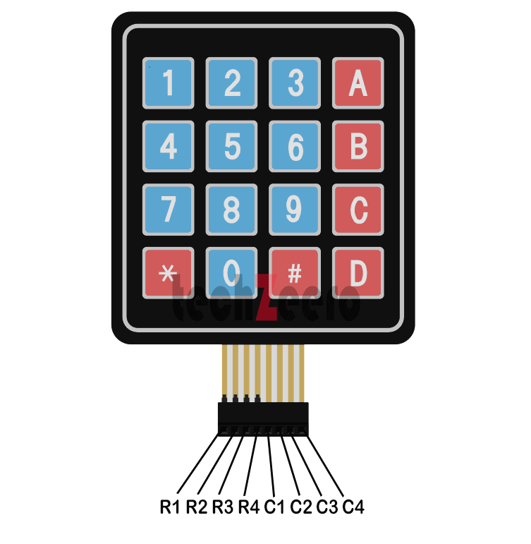
Keypad Pinout
The keypad typically consists of multiple rows and columns, each connected to a specific pin on the Arduino board. By identifying these pins, you can effectively communicate with the keypad.
The pinout configuration may vary depending on the type of keypad you are using – whether it’s a 4×4 or 4×3 matrix. For instance, in a 4×3 matrix keypad, there are 7 pins in total: 3 for rows and 4 for columns. On the other hand, a 4×4 matrix has 8 pins: 4 for rows and 4 for columns.
Working of Keypad Matrix
A keypad matrix is essentially a grid of buttons where each button corresponds to a unique row and column intersection. By pressing a button, you complete an electrical connection between the specific row and column. When we pressed a key it closes the switch and allows the current flow between column and row pin.
- Normally when no button is pressed all the row pins are held LOW and all the column pins are held HIGH.
- When the button is pressed the column is held at LOW.
- Now Arduino knew the column button, its time to find the row from the button is. Now the row pins switched to HIGH
- When the column pin rises again HIGH, Arduino finds the row pin that is connected to the button.
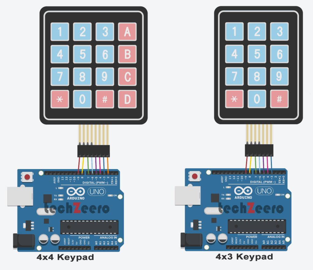
Pin Connection of Keypad with Arduino
Connect the Keypad pins with Arduino as follow. Skip the last one for the 4×3 keypad matrix.
| Keypad Pins | Arduino Pins |
|---|---|
| R1 | 9 |
| R2 | 8 |
| R3 | 7 |
| R4 | 6 |
| C1 | 5 |
| C2 | 4 |
| C3 | 3 |
| C4 | 2 |
Circuit Diagram of Keypad Matrix with Arduino
The keypad matrix consists of rows and columns that intersect at each key, allowing the Arduino to detect which key has been pressed.
To create the circuit diagram, connect one side of each button in a row to an input pin on the Arduino and the other side of each button in a column to an output pin. This setup enables the Arduino to scan through each row and column to determine which key is being pressed.
Code for 4×4 Keypad with Arduino
Setting up a 4×4 keypad with Arduino involves writing code that allows the Arduino to interpret the key presses on the keypad. Each key press corresponds to a specific value or character, enabling users to input data or trigger actions in their projects.
To begin, you will need to define the pins connecting the keypad to the Arduino. By mapping out these connections, you can effectively communicate with the keypad and receive input from it.
Next, create an array that represents the layout of your 4×4 keypad. This array will help translate physical key presses into usable data for your Arduino program.
Utilize conditional statements in your code to determine which key has been pressed at any given time. Based on this information, you can implement various functions or commands within your project.
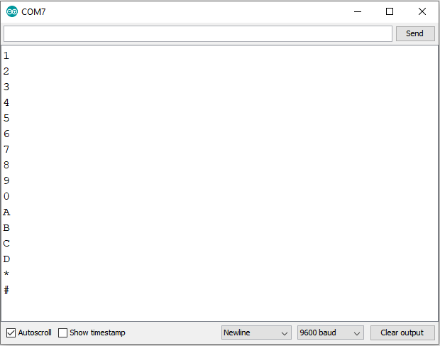
Upload the below code and open the serial monitor. Now press keys and you can see the output key in the serial monitor.
Code for 4×3 Keypad Matrix
Now, let’s dive into the exciting world of coding for a 4×3 keypad matrix with Arduino.
To begin, you will need to write a code that maps out the connections between the rows and columns of the keypad matrix. This mapping will allow the Arduino to recognize which key has been pressed based on the corresponding row and column intersection.
Next, you can assign specific functions or actions to each key on the 4×3 keypad.
Output
Once you have successfully set up the keypad with your Arduino board, it’s time to see the output in action. Pressing different keys on the keypad will trigger corresponding actions programmed in your Arduino code. Each key press will generate a unique signal that is read by the Arduino, allowing you to interact with your project in a tangible way.
Open the serial monitor to see the output while pressing a key.
Troubleshooting Common Issues
Encountering issues while setting up a keypad with your Arduino? Don’t worry, troubleshooting common problems can help you get back on track smoothly.
- One common issue is incorrect wiring – double-check the connections to ensure they are properly aligned with the keypad pinout. If the keypad isn’t responding, verify that the code matches the wiring configuration for your specific keypad matrix.
- Another potential problem could be ghosting or keys registering multiple inputs simultaneously. This may indicate a hardware or software issue that requires debugging.
- Additionally, if certain keys are not registering at all, it could be due to a faulty connection or programming error that needs attention.
- Remember to check for any loose wires, damaged components, or coding errors that might be causing disruptions in communication between the keypad and Arduino board.
Creative uses for a keypad on an Arduino
Have you ever thought about using a keypad on your Arduino for more than just entering numbers or passwords? Get ready to explore some creative uses that will take your projects to the next level!
- One innovative idea is creating a DIY security system where users have to enter a specific code to access something valuable. Imagine building a secret box that only opens when the correct sequence is entered – perfect for hiding treasures or surprises.
- Another fun application is designing interactive games with the keypad as a controller. From classic Snake and Simon Says games to custom-made puzzles, the possibilities are endless. Challenge yourself by programming unique gameplay mechanics that engage players of all ages.
- You can also use the keypad for menu navigation in electronic devices like digital clocks or mini calculators. Simplify user interaction by allowing them to input data quickly and efficiently using the keypad’s tactile buttons.