Introduction to Vibration Motor
Introducing the world of vibration motor with Arduino opens up a realm of possibilities for dynamic projects and interactive applications. In this blog, we will learn to interface a vibration motor with Arduino.
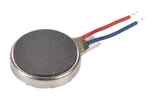
Vibration motors are compact, versatile devices capable of producing controlled vibrations, making them ideal for haptic feedback, alert mechanisms, and tactile interfaces. It will produce no sound.
Mainly they are used in mobile phones, joysticks, pager and so on.
Must See
Components Needed
- Arduino.
- Vibration Motor.
- NPN Transistor.
- Resistors.
- Wires.
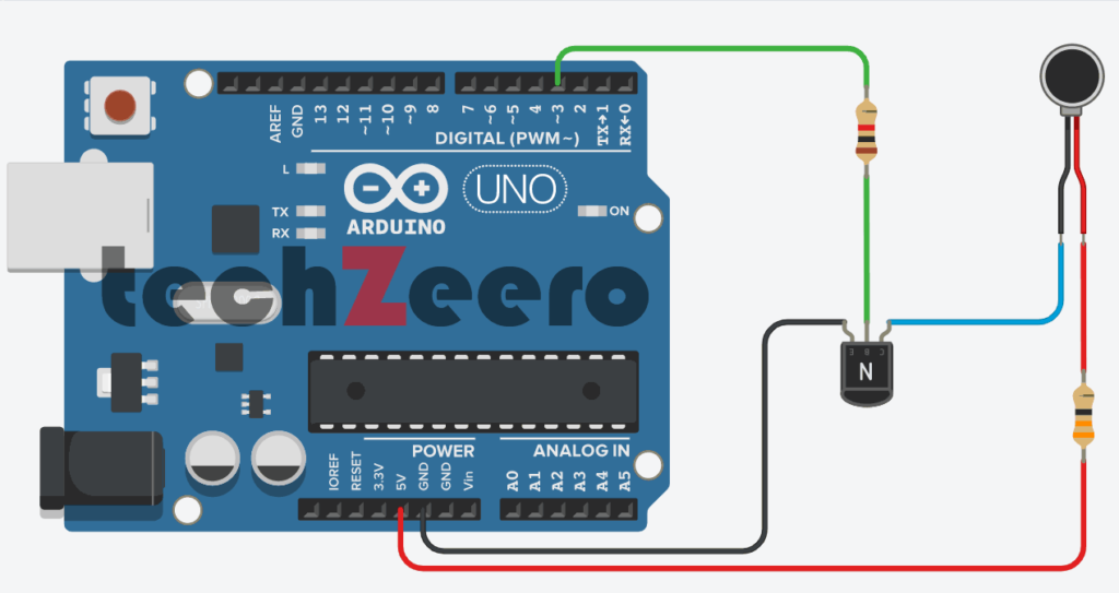
Circuit Diagram for Vibration Motor with Arduino
To start, place the vibration motor on a breadboard and connect one of its terminal to 5V on the Arduino board with a resistor in between.
Next, attach the ground (GND) terminal of the vibration motor to a NPN transistor collector (C) terminal. Connect the NPN base (B) terminal with Arduino digital pin 3 with a resistor in between. And the emitter (E) terminal of NPN transistor should be connect with Arduino GND pin.
Ensure that you have properly connected all necessary wires and components according to the circuit diagram.
Code
In order to program the vibration motor with Arduino, you will need to define the pins used for input and output connections. This involves assigning values to variables and specifying the duration and intensity of vibrations.
The following sketch will turn on the vibration motor for one second each minute:
This sketch uses a motor designed to vibrate. If you have an old cell phone which no longer needed, it may contain tiny vibration motors that would be suitable.
Vibration motors require more power than an Arduino pin can provide, so a transistor is used to switch the motor current on and off. Any NPN transistor can be used.
A 1 kilohm resistor connects the output pin to the transistor base; the value is not critical, and you can use values up to 4.7 kilohms or so (the resistor prevents too much current flowing through the output pin).
The diode absorbs voltages produced by the motor windings as it rotates. The capacitor absorbs voltage spikes produced when the brushes (contacts connecting electric current to the motor windings) open and close.
The 33-ohm resistor is needed to limit the amount of current flowing through the motor.
This sketch sets the output pin HIGH for one second (1000 milliseconds) and then waits for 50 seconds. The transistor will turn on (conduct) when the pin is HIGH, allowing current to flow through the motor.
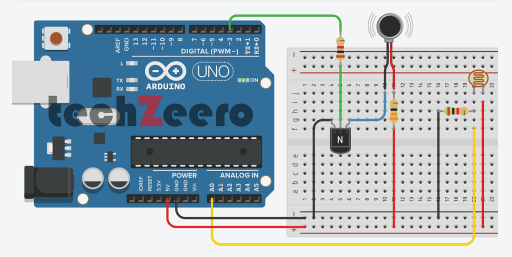
Vibration Motor and LDR Sensor
To add a new dimension to your Arduino projects, consider combining a vibration motor with an LDR sensor. This innovative pairing allows you to create interactive devices that respond to light intensity by triggering vibrations.
Must See
To connect a vibration motor and LDR with Arduino, simply include the LDR connection to analog pin 0.
Code
The code for this setup involves creating a program that allows the Arduino to control the vibration motor based on the input received from the LDR sensor.
In your Arduino IDE, you will need to write code that reads the analog value from the LDR sensor and maps it to control the speed or intensity of the vibration motor. This mapping ensures that as light levels change, so does the vibration strength of the motor.
By utilizing conditional statements in your code, you can set thresholds for different light levels detected by the LDR sensor.
Here the output pin is turned on when a light shines on the photocell. When the sketch starts, the background light level on the sensor is read and stored in the variable sensorAmbient.
Light levels read in the loop that is higher than this will turn on the vibration motor.
Troubleshooting Common Issues
If you encounter issues with your vibration motor and Arduino setup, don’t worry, as troubleshooting common problems can help resolve them quickly.
- One common issue could be improper connections or loose wires. Ensure all connections are secure and properly inserted into the correct pins on the Arduino board.
- Another potential problem could arise from a faulty vibration motor. Check if the motor is running smoothly by testing it separately without connecting to the Arduino. If it doesn’t vibrate, consider replacing it with a new one.
- Additionally, software-related issues like incorrect code syntax or missing libraries could cause the vibration motor not to function correctly. Double-check your code for any errors and ensure that you have included all necessary libraries for driving the motor.
- Power supply issues such as insufficient voltage or current may also impact the performance of the vibration motor. Make sure you provide an adequate power source to drive the motor effectively and avoid any fluctuations in power that could disrupt its operation.
Applications of Vibration Motor with Arduino
Vibration motors with Arduino have a wide range of applications across various industries.
- One common use is in haptic feedback systems, where the motor provides tactile feedback to users in devices like smartphones and gaming controllers. This enhances the user experience by adding a sense of touch to interactions.
- In robotics, vibration motors can be utilized for alert systems or notifications. For example, a robot can use vibrations to signal low battery levels or completion of a task without requiring visual or auditory cues. This makes the communication between humans and robots more efficient and intuitive.
- Moreover, vibration motors are also employed in wearable technology such as smartwatches and fitness trackers. They can deliver discreet alerts for incoming calls, messages, or activity reminders without disturbing the user’s surroundings.