Introduction to DC Motor with Arduino
In this tutorial, we will learn how to interface a DC motor with Arduino. We can make things move by controlling motors with Arduino. In this article, we will interface multiple motors and control their speeds.
DC Motors are also known as Brushed and Brushless Motors.
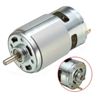
Most low-cost direct current (DC) motors are simple devices with two leads connected to brushes (contacts) that control the magnetic field of the coil that drives a metallic core (armature).
The direction of rotation can be reversed by reversing the polarity of the voltage on the contacts.
DC motors are available in many different sizes, but even the smallest (such as vibration motors used in cell phones) require a transistor or other external control to provide adequate current.
The recipes that follow to show how to control motors using a transistor or an external control circuit called H-Bridge.
Must See
Components Needed
- Arduino.
- DC Motors.
- L293D H-Bridge IC.
- Breadboard.
- Jumper Wires.
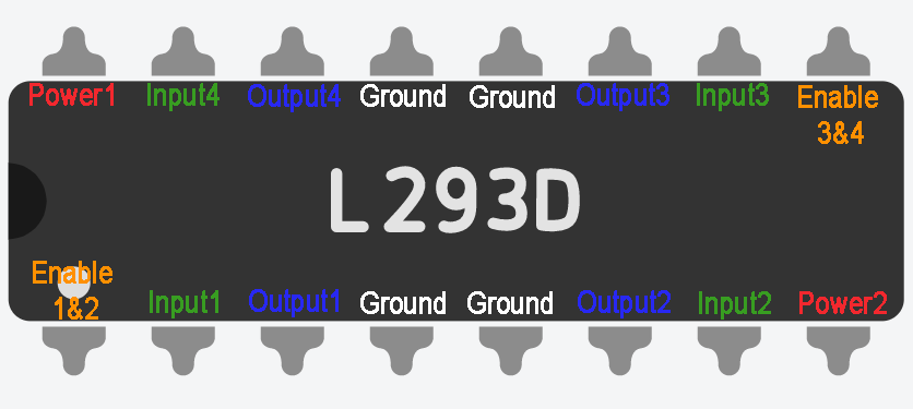
L293D H-Bridge IC
The L293D H-Bridge IC is a versatile and essential component when working with DC motors in Arduino projects. This integrated circuit allows bidirectional control of the motor, enabling it to rotate in both directions.
With its dual H-bridge design, the L293D can drive two motors simultaneously. It simplifies the process of controlling motor direction by providing an easy interface for Arduino microcontrollers.
By utilizing the L293D H-Bridge IC, you can easily control the speed and direction of your DC motors with just a few lines of code. Its ability to handle high voltage and current makes it suitable for a wide range of applications beyond basic robotics and automation projects.
Note: We can also use the SN754410 which has the same pin layout.
Controlling the Direction of a DC Motor with an H-Bridge
DC motors are widely used in various projects, and controlling their direction with an H-Bridge is a common practice among Arduino enthusiasts. The L293D H-Bridge IC plays a crucial role in this process, allowing the motor to rotate forward or backward based on the signals received from the Arduino board.
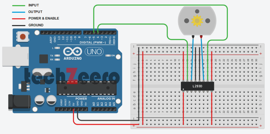
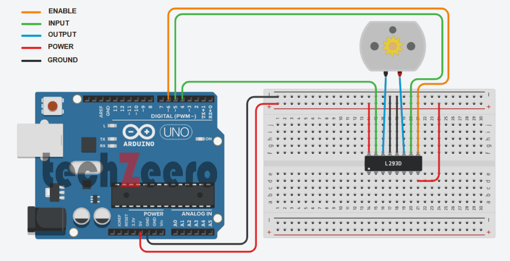
Circuit Diagram for controlling direction of a DC Motor
To control the direction of a DC motor using an H-Bridge, you need to understand how to wire the components correctly. By sending specific signals through the Arduino pins connected to the H-Bridge, you can change the polarity of the voltage applied to the motor terminals, thus determining its rotation direction.
Code for controlling direction of a DC Motor
In order to control a DC motor using Arduino, you need to write a simple program that specifies the direction and speed of rotation. This can be achieved by sending signals to the H-Bridge IC connected to the motor.
The following sketch controls the direction of a DC motor with H-Bridge:
The table shows how the values on the H-Bridge input affect the motor. In the solution a single motor is controlled using the IN1 & IN2 pins; the EN pin is permanently HIGH because it is connected to +5V.
| EN | IN1 | IN2 | Function |
|---|---|---|---|
| HIGH | LOW | HIGH | Turn Clockwise |
| HIGH | HIGH | LOW | Turn Anticlockwise |
| HIGH | LOW | LOW | Motor Stop |
| HIGH | HIGH | HIGH | Motor Stop |
| LOW | Ignored | Ignored | Motor Stop |
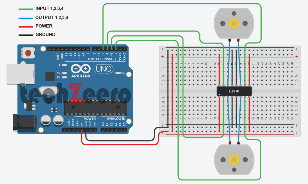
Controlling the Direction of Two DC Motor with Arduino
Controlling the direction of two DC motors with Arduino opens up a world of possibilities for your projects. By using an H-Bridge IC like L293D, you can easily manage the rotation of both motors independently. This means you can create more complex movements and interactions in your designs.
Circuit Diagram
Now connect one more motor in the same circuit.
Code
With a solid understanding of coding and circuitry, you can program each motor to move forward, backward, or stop based on your requirements. Whether it’s building a robot that maneuvers through obstacles or a remote-controlled car that races around corners, the ability to control two motors separately adds versatility to your creations.
The following sketch controls both motors together:
Controlling the direction and speed of a DC motor with an H-Bridge
When it comes to controlling the direction and speed of a DC motor with an H-Bridge, you are entering the exciting realm of robotics and automation. The H-Bridge acts as a crucial component that allows you to change the polarity of the voltage applied to the motor, determining its rotation direction.
By adjusting the input signals sent to the H-Bridge from your Arduino board, you can not only control which way the motor spins but also regulate its speed. This level of precision opens up endless possibilities for creating dynamic projects that require precise movement control.
This extends the functionality by controlling both motor direction and speed through a command from the serial port.
Circuit Diagram
Code
This sketch uses commands from the Serial Monitor to control the speed and direction of the motor.
Sending “0” will stop the motor, and digits “1” through “9” will control the speed. Sending “+” and “-” will set the direction of motor:
Motor direction is controlled by the levels on the IN1 & IN2 pins. But in addition, speed is controlled by the analogWrite value on the EN pin.
Writing a value of 0 will stop the motor; wiring 255 will run the motor at full speed. The motor speed will vary in proportion to values within this range.
Using Sensor to control the Direction and Speed of DC Motors
Imagine a world where your DC motors respond to the environment around them. With Arduino and sensors, this dream becomes a reality. By incorporating sensors like ultrasonic or infrared into your project, you can control the direction and speed of your DC motors based on real-time data.
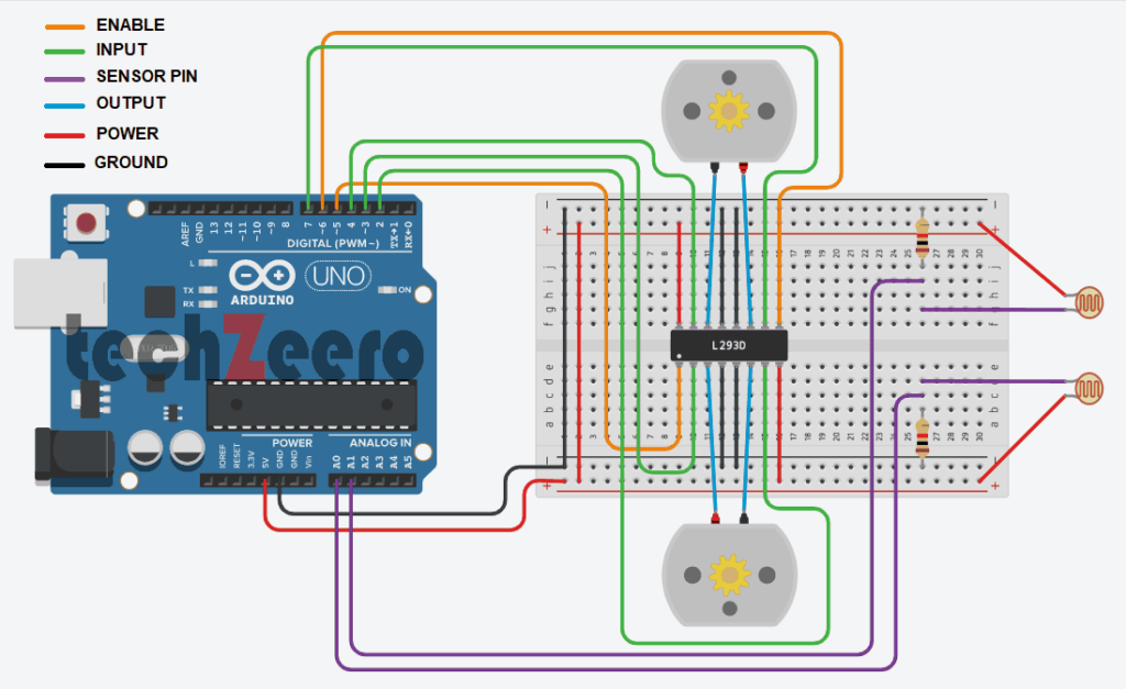
Lets control the direction and speed of dc motors with feedback from sensors. For example, we want two photo sensors to control motor speed and direction to cause a robot to move toward a beam of light.
This solution uses two motor connection, with the addition of two light-dependent resistors, as shown in the figure.
Must See
Circuit Diagram
Code
The sketch monitors the light level on the sensors and drives the motors towards the sensor detecting the brighter light level:
This sketch controls the speed of two motors in response to the amount of light detected by two photocells.
When an increase in light on one side will increase the speed of the motor on the other side.
This causes the robot to turn toward the side with the brighter light. Light shining equally on both cells makes the robot move forward in a straight line. Insufficient light causes the robot to stop and look around to see if there is a light source coming from any other direction.
Light is sensed through analog input 0 & 1. When the program starts, the ambient light is measured and this threshold is used to determine the minimum light level needed to move the robot. When the light drops below the threshold, the lookAround function is called to rotate the robot to search for more light.
Motor speed is controlled in the setSpeed function. Two pins are used to control the direction for each motor and with another pin to control speed. The pin number is held in the leftPins and rightPins arrays. The first pin in each array is the speed pin; the other two pins are for direction.
Troubleshooting Common Issues
Having trouble with your DC motor project using Arduino? Don’t worry, common issues can arise, but solutions are within reach.
- If your motor isn’t running, check the wiring connections first. Make sure everything is properly connected to avoid any loose wires causing disruptions.
- Another common issue could be incorrect code implementation. Double-check your code for any typos or errors that might be preventing the motor from functioning correctly.
- Voltage supply problems can also cause issues with the motor’s performance. Ensure that you are providing the correct voltage and current for optimal operation.
- If all else fails, consider troubleshooting step by step to identify and address any other potential issues affecting your DC motor project’s functionality.
Applications of DC Motor with Arduino
DC motors with Arduino have a wide range of applications across various fields.
- In robotics, DC motors are commonly used for controlling movement and positioning of robotic arms or vehicles. They play a crucial role in the automation industry, powering conveyor belts, pumps, and other machinery.
- In the field of home automation, DC motors integrated with Arduino can automate tasks such as opening and closing curtains, windows, or doors. This technology is also utilized in agriculture for automating irrigation systems to ensure efficient water distribution.
- Moreover, DC motors with Arduino find their place in the automotive industry for controlling components like windshield wipers or adjusting mirrors. Hobbyists often use them in DIY projects like building remote-controlled cars or drones.