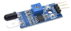
What is the IR Sensor or Infrared Obstacle Sensor Module
IR Sensor Module has built-in an IR transmitter and IR receiver that sends out infrared light and looks for reflected infrared light to detect the presence of any obstacle in front of the sensor module.
It is used to find obstacles and short & medium-range communication.
There is onboard a potentiometer to adjust the detection range. There is an Obstacle Detection LED indicator on the module board.
IR sensor transmits digital data (logical 1 and 0) in the form of infrared light. When the sensor gets logical 1 means LED ON and logical 0 means LED OFF.
The sensor has a very good and stable response even in ambient light or in complete darkness.
Related Article: How to interface IR Sensor with Arduino
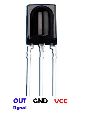
IR Sensor Pinout
Typically, an IR sensor will have three pins – VCC (power supply), GND (ground), and OUT (output signal).
The VCC pin is where you connect the positive terminal of your power source, while the GND pin is for connecting the negative terminal.
The OUT pin is where you receive the output signal from the sensor based on its detection of infrared radiation.
It also has a potentiometer to adjust obstacle distance.
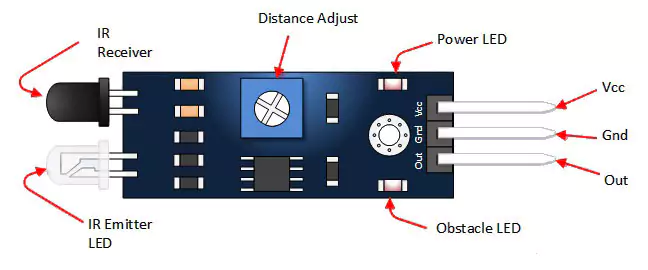
Pin Description
| Vcc | 3.3 to 5 Vdc Supply Input |
| GND | Ground Input |
| Out | The output that goes low when an obstacle is in range |
| Power LED | Illuminates when power is applied |
| Obstacle LED | Illuminates when an obstacle is detected |
| IR Emitter | Infrared emitter LED |
| IR Receiver | The infrared receiver that receives signal transmitted by Infrared emitter. |
Working Principle of IR Sensor
The working principle of an IR sensor is fascinating. These sensors detect infrared radiation emitted by objects in their vicinity. When an object emits heat, it generates infrared radiation that the sensor can pick up. This detection process allows the sensor to identify the presence or absence of an object based on its heat signature.
IR sensors consist of a transmitter and a receiver. The transmitter emits infrared light, which bounces off nearby objects and gets reflected back to the receiver. By measuring the time it takes for the signal to return, the sensor can determine proximity and detect motion.
This technology is widely integrates in various applications such as security systems, automatic doors, and proximity sensors in smartphones.
Specifications
These sensors typically operate in wavelengths between 0.7 to 14 micrometers, making them ideal for various applications.
Additionally, many modern IR sensors come equipped with adjustable detection ranges and output signals, providing flexibility in designing systems that meet specific requirements. Some models even include built-in filters to minimize interference from ambient light sources.
| Board Size | 3.2 x 1.4cm |
| Working voltage | 3.3 to 5V DC |
| Operating voltage | 3.3V: ~23 mA, to 5V: ~43 mA |
| Detection range | 2cm – 30cm (Adjustable using potentiometer) |
| Active output level | The output is “0” (Low) when an obstacle is detected |
Hardware Connections
- Vcc to 5V of Arduino.
- GND to GND of Arduino.
- Out to any digital pin of Arduino.
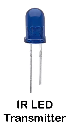
IR Transmitter
- For transmitting IR LED of wavelength 940 nm to 950 nm are commonly used.
- This IR LED transmits the data from one end to and at another end there is an IR receiver to receive the data.
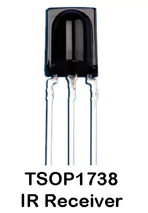
IR Receiver TSOP1738
- At the receiver end, the IR receiver receives data at 38kHz of the carrier frequency.
- Mainly, TSOP Receiver is use to receive data which support various transmitted code.
- The data rate of TSOP1738 is up to 2400 bps.